160 Rockwell Automation Publication 750-PM001N-EN-P - February 2017
Chapter 3 Drive Port 0 Parameters
DIAGNOSTICS
Status
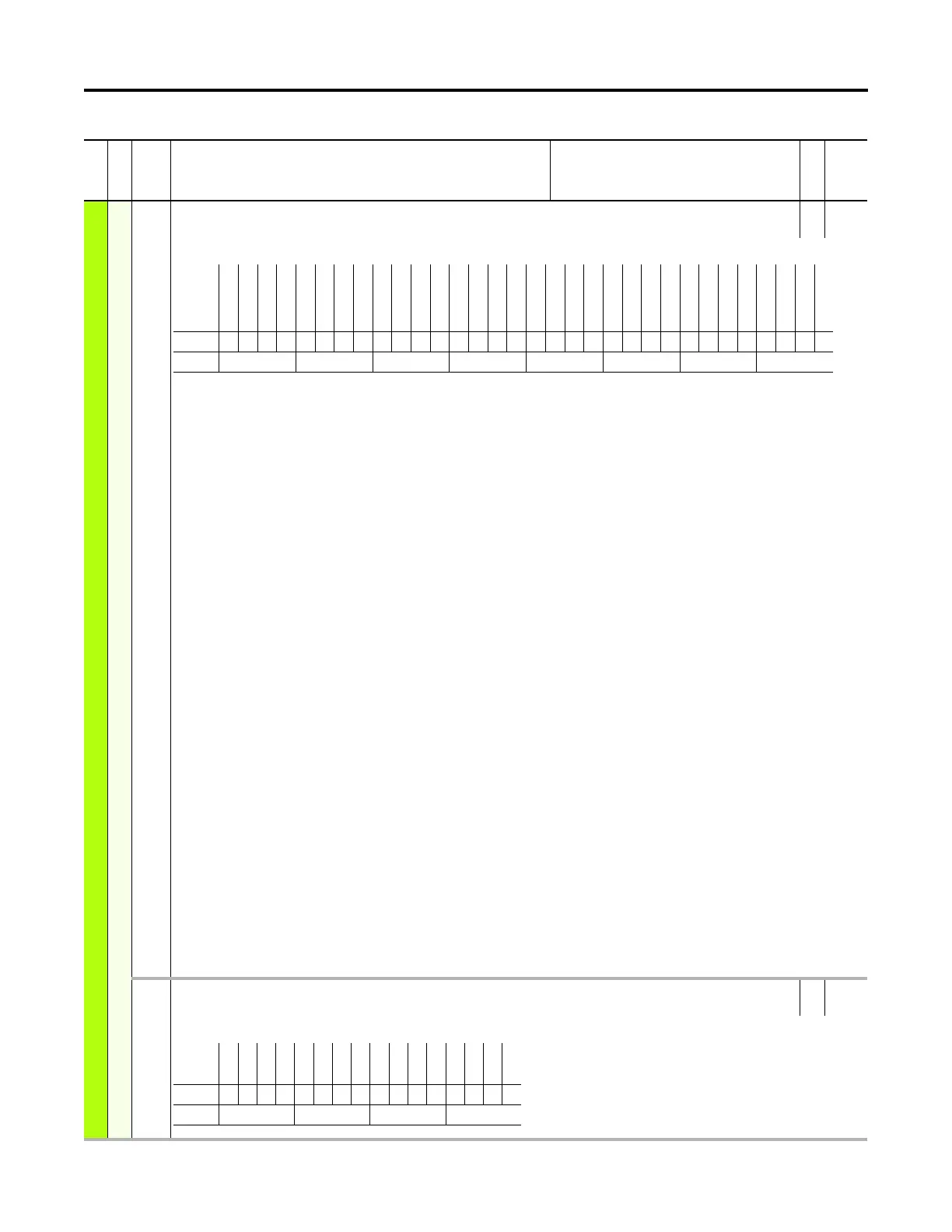
945 At Limit Status
At Limit Status
RO 32-bit
Integer
Status of dynamic conditions within the drive that are either active or a limit is being applied.
Bit 0 “Current Lmt” – Scalar current limit is adjusting the output frequency
Bit 1 “Bus Vltg Lmt” – Scalar bus voltage limit is adjusting the output frequency
Bit 2 “MaxSpeed Lmt” – Motor speed reference is limited to maximum forward speed or maximum reverse speed. See P520 [Max Fwd Speed], P521 [Max Rev
Speed].
Bit 3 “OverSpd Lmt” – Motor speed reference positive (+) trim is at maximum speed limit plus or minus (+/-) the overspeed limit
Bit 4 “Spd Reg Lmt” – The output of the drive’s speed regulator has reached limit. See P655 [Spd Reg Pos Lmt], P656 [Spd Reg Neg Lmt].
Bit 5 “Freq Hi Lmt” – Scalar control inner ramp high limit is active
Bit 6 “Freq Lo Lmt” – Scalar control inner ramp low limit is active
Bit 7 “FreqOSPosLmt” – Scalar control inner ramp positive (+) overspeed limit is active
Bit 8 “FreqOSNegLmt” – Scalar control inner ramp negative (-) overspeed limit is active
Bit 9 “Flux Braking” – Flux braking is active
Bit 10 “Economize” – Economize is active
Bit 11 “PWM FreqLmt” – PWM frequency is reduced by the thermal regulator
Bit 12 “DB Res Limit” – Dynamic brake thermal protection is active. Verify P385 [DB ExtPulseWatts].
Bit 13 “PsnReg LoLmt” – The position integrator low limit is active
Bit 14 “PsnReg HiLmt” – The position integrator high limit is active
Bit 15 “PsnReg LoSpd” – The position regulator output (speed) is at low limit
Bit 16 “PsnReg HiSpd” – The position regulator output (speed) is at high limit
Bit 17 “TrqCurPosLmt” – The torque current positive limit is active
Bit 18 “TrqCurNegLmt” – The torque current negative limit is active
Bit 19 “FlxCurPosLmt” – The flux current positive limit is active
Bit 20 “FlxCurNegLmt” – The flux current negative limit is active
Bit 21 “Trq Pos Lmt” – The positive torque limit is active. See P670 [Pos Torque Limit].
Bit 22 “Trq Neg Lmt” – The negative torque limit is active. See P671 [Neg Torque Limit].
Bit 23 “Mtrng PwrLmt” – The motoring power limit is active. See P427 [Motor Power Lmt].
Bit 24 “Regen PwrLmt” – The regeneration power limit is active. See P426 [Regen Power Lmt].
Bit 25 “Cur Lmt FV” – The current limit parameter or analog Input current limit is active
Bit 26 “Therm RegLmt” – The thermal regulator torque limit is active
Bit 27 “BusVltgFVLmt” – The bus voltage regulator torque limit is active
Bit 28 “Mtr Vltg Lkg” – The Vds motor voltage limit is active
Bit 29 “TrqPrvPosLmt” – The torque proving positive torque limit is active
Bit 30 “TrqPrvNegLmt” – The torque proving negative torque limit is active
Bit 31 “Cur Rate Lmt” – The Iqs rate limit is active
946 Safety Port Sts
Safety Port Status
RO 16-bit
Integer
Indicates the port location of a valid feedback option for use with the Safe Speed Monitoring Option.
File
Group
No. Display Name
Full Name
Description
Values
Read-Write
Data Type
Options
Cur Rate Lmt
TrqPrvNegLmt
TrqPr vPosLmt
Mtr Vltg Lkg
BusVltgFVLmt
Therm RegLmt
Cur Lmt FV
Regen PwrLmt
Mtrng PwrLmt
Trq Neg Lmt
Trq Pos Lmt
FlxCurNegLmt
FlxCurPosLmt
TrqCurNegL mt
TrqCurPo sLmt
PsnReg HiSpd
PsnReg LoSpd
PsnReg HiLmt
PsnReg LoLmt
DB Res Limit
PWM FreqLmt
Economize
Flux Braking
FreqOSNegLmt
FreqOSPosLmt
Freq Lo Lmt
Freq Hi Lmt
Spd Reg Lmt
OverSpd Lmt
MaxSpeed Lmt
Bus Vltg Lmt
Current Lmt
Default00000000000000000000000000000000
Bit 313029282726252423222120191817161514131211109876543210
0 = Condition False
1 = Condition True
Options
Reserved
Reserved
Reserved
Reserved
Reserved
Reserved
Reserved
Port 8
Port 7
Port 6
Port 5
Port 4
Reserved
Reserved
Reserved
Reserved
Default0000000000000000
Bit 1514131211109876543210
0 = Condition False
1 = Condition True
 Loading...


