Rockwell Automation Publication 750-PM001N-EN-P - February 2017 225
Port 10 and Port 11 Parameters Chapter 4
Precharge n (Port 11)
Parameters
Precharge n parameters apply only to PowerFlex 755 Common DC Input Frame
8 and larger drives.
File
Group
No. Display Name
Full Name
Description
Values
Read-Write
Data Type
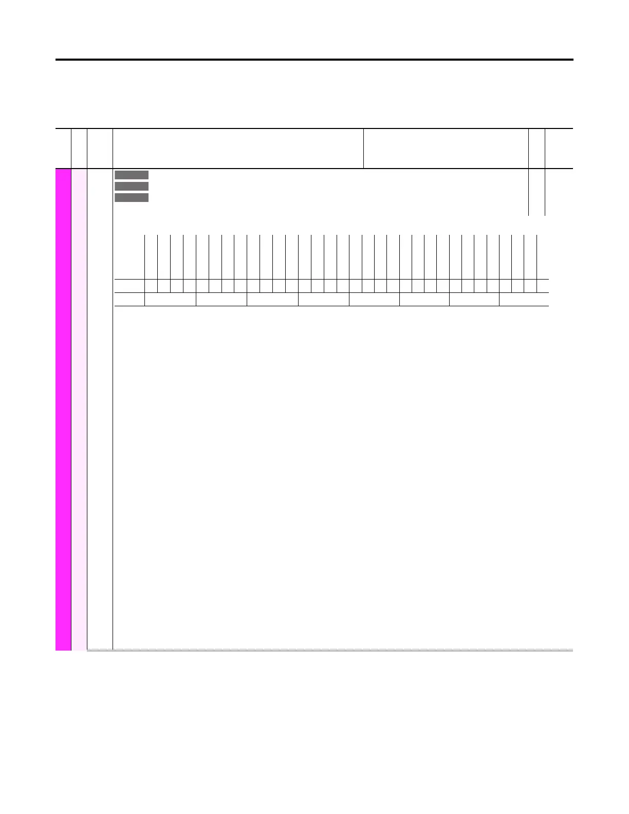
PRECHARGE N
Status
104
204
304
P1 Board Status
P2 Board Status
P3 Board Status
Precharge n Board Status
RO 32-bit
Integer
Status bits for the precharge board.
Bit 0 “Ready” – CB controller is ready to begin the precharge sequence. Stop input is not active, 240V AC is present, molded case switch (MCS) auxiliary contact is
open, disconnect is closed and there are no faults.
Bit 1 “MCS Closing” – The precharge sequence is in progress but is not complete.
Bit 2 “Prechrg Done” – Precharge has been completed and the MCS is closed.
Bit 3 “MCS Opening” – The MCS is in the process of opening.
Bit 4 “Faulted” – A fault has occurred and is enumerated in the fault word.
Bit 5 “Alarm” – An alarm has occurred and is enumerated in the alarm word.
Bit 7 “240V ACPresnt” – 240V AC supply is present. Threshold is 85% or 204V AC.
Bit 8 “DC Bus OK” – 0 = DC bus voltage out of tolerance. 1 = DC bus voltage is within tolerance.
Bit 9 “Discnnct In” – 0 = Auxiliary switch is off. 1 = Auxiliary switch is on.
Bit 10 “Discnnct Out” – 0 = Relay is off. 1 = Relay is on.
Bit 11 “BusPosFuseIn” – 0 = Fuse is blown. 1 = Fuse is intact.
Bit 12 “BusNegFuseIn” – 0 = Fuse is blown. 1 = Fuse is intact.
Bit 13 “DoorLock In” – 0 = Door is open. 1 = Door is closed.
Bit 14 “DoorLock Out” – 0 = Door solenoid relay is off. 1 = Door solenoid relay is on.
Bit 15 “Fan Out” – 0 = Fan is on. 1 = Fan is off.
Bit 16 “Ext Opn/Cls” – 0 = Inactive (tied to common or open). 1 = Active (24V DC applied).
Bit 17 “Ext Inhibit” – 0 = Stopped (tied to common or open). 1 = Not Stopped (24V DC applied). Level sensitive. Ignored when fiber-optic communications is
online.
Bit 18 “Ext FaultRst” – 0 = Inactive (tied to common or open). 1 = Active (24V DC applied).
Bit 19 “MCSCIsCilOut” – 0 = Relay is off. 1 = Relay is on.
Bit 20 “MCSShntRelOt” – 0 = Relay is off. 1 = Relay is on.
Bit 21 “MCSSprgChgOt” – 0 = Relay is off. 1 = Relay is on.
Bit 22 “MCS UVDlyOut” – 0 = Relay is off. 1 = Relay is on.
Bit 23 “MCS AuxInput” – 0 = MCS auxiliary contact is open. 1 = MCS auxiliary contact is closed.
Bit 24 “Flash Failed” – An error occurred during the flash update process.
Bit 30 “Flash Update” – The precharge controller is in flash update mode.
Bit 31 “ReadyToReset” – The flash update process has ended and the precharge controller is waiting for a reset command.
Options
ReadyToReset
Flash Update
Reserved
Reserved
Reserved
Reserved
Reserved
Flash Failed
MCS AuxInput
MCS UVDlyOut
MCSSprgChgOt
MCSShntRelOt
MCSCIsCilOut
Ext FaultRst
Ext Inhibit
Ext Opn/Cls
Fan Out
DoorLock Out
DoorLock In
BusNegFuseIn
BusPosFuseIn
Discnnct Out
Discnnct In
DC Bus OK
240V ACPresnt
Reserved
Alarm
Faulted
MCS Opening
Prechrg Done
MCS Closing
Ready
Default00000000000000000000000000000000
Bit 313029282726252423222120191817161514131211109 8 7 6 5 4 3 2 1 0
0 = False
1 = True
 Loading...


