EasyManuals Logo

Allen-Bradley PowerFlex 20-750-DCBB2-F6 Programming Manual

Allen-Bradley PowerFlex 20-750-DCBB2-F6
548 pages
To Next Page IconTo Next Page
To Previous Page IconTo Previous Page
Page #396 background imageLoading...
Page #396 background image
396 Rockwell Automation Publication 750-PM001N-EN-P - February 2017
Appendix B PowerFlex 755 Control Block Diagrams
Diagram Conventions and
Definitions
11-Series Inputs & Outputs - ATEX 432
Control Logic 433
Inverter Overload IT 434
Friction Compensation 435
Variable Boost Voltage Overview - Function Inputs/Outputs 436
Diagnostic Tools 437
High-Speed Trend Wizard 438
Diagram Page
Denitions of the Per Unit system:
1.0 PU Position = Distance traveled / 1sec at Base Spd
1.0 PU Speed = Base Speed of the Motor
1.0 PU Torque = Base Torque of the Motor
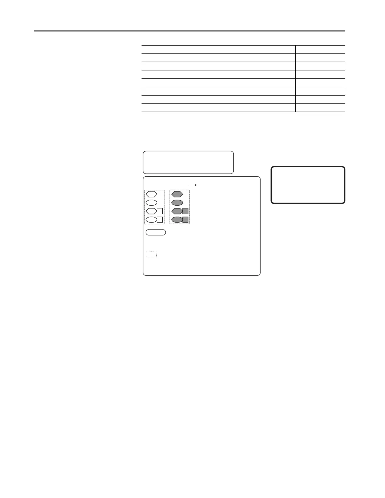
Read Only Parameter with Bit Enumeration
Read / Write Parameter with Bit Enumeration
Provides additional information
Read Only Parameter
Read / Write Parameter
Symbol Legend:
* Notes, Important :
(1) These diagrams are for reference only and may
not accurately reect all logical control signals;
actual functionality is implied by the approximated
diagrams. Accuracy of these diagrams is not
guaranteed.
Drive
Parameters
Option Module
Parameters
Requires port number.
( ) = Enumerated Parameter
[ ] = Page and Coordinate
ex. 3A2 = pg 3, Column A, Row 2
= Constant value
‘d’ = Prex refers to Diagnostic Item Number
ex. d33 = Diagnostic Item 33

Table of Contents

Other manuals for Allen-Bradley PowerFlex 20-750-DCBB2-F6

Questions and Answers:

Question and Answer IconNeed help?

Do you have a question about the Allen-Bradley PowerFlex 20-750-DCBB2-F6 and is the answer not in the manual?

Allen-Bradley PowerFlex 20-750-DCBB2-F6 Specifications

General IconGeneral
BrandAllen-Bradley
ModelPowerFlex 20-750-DCBB2-F6
CategoryController
LanguageEnglish

Related product manuals