Rockwell Automation Publication 750-PM001N-EN-P - February 2017 213
Port 10 and Port 11 Parameters Chapter 4
INVERTER COMMON
Status
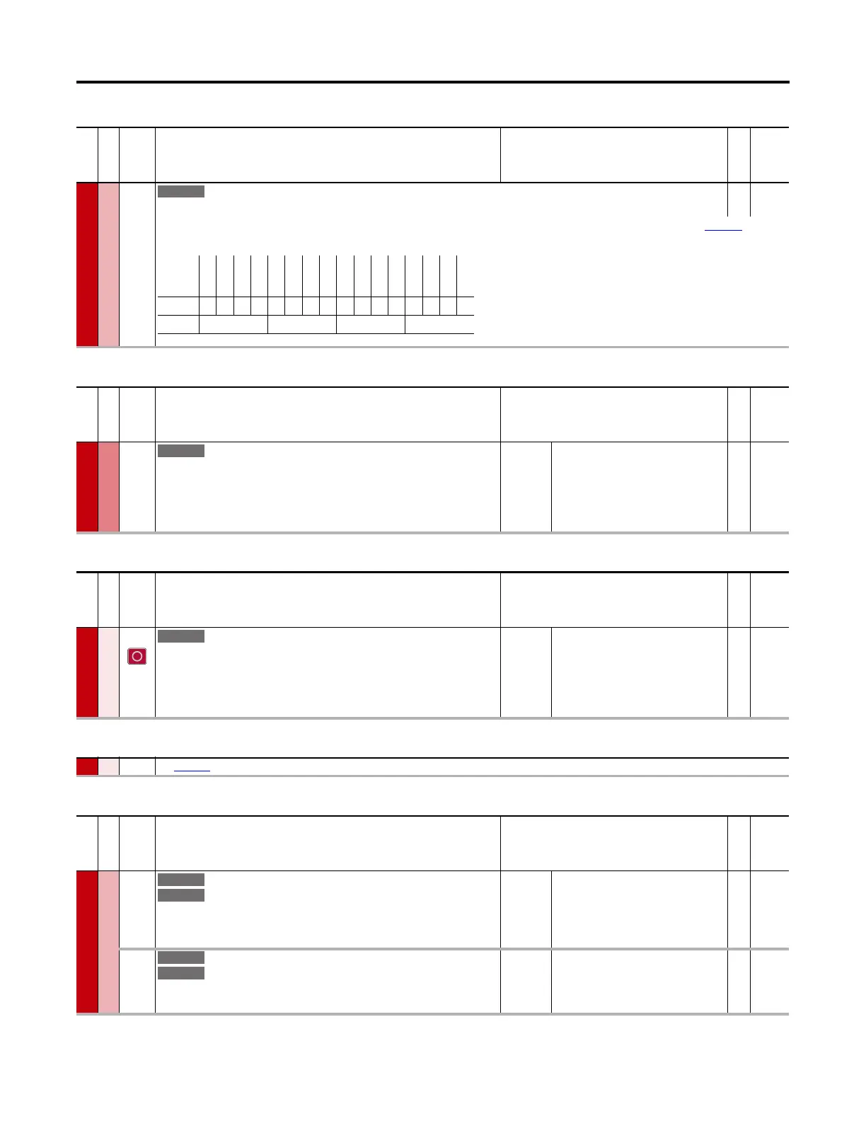
13 Alarm Status
Alarm Status
RO 16-bit
Integer
Indicates whether the inverter has an alarm condition. See P107 [I1 Alarm Status] to view which alarms currently exist for inverter 1. Refer to Chapter
6 for
information on fault and alarm codes.
File
Group
No. Display Name
Full Name
Description
Values
Read-Write
Data Type
Options
Reserved
Reserved
Reserved
Reserved
Reserved
Reserved
Reserved
Reserved
Reserved
Reserved
Reserved
Reserved
Reserved
Reserved
Inverter 2
Inverter 1
Default0000000000000000
Bit 1514131211109876543210
0 = No Alarm
1 = Alarm
File
Group
No. Display Name
Full Name
Description
Values
Read-Write
Data Type
INVERTER COMMON
Metering
18 Ground Current
Ground Current
Ground current of AC output to a motor. This value is calculated based on the total
output currents (U, V, and W phases of the drive). When the three phases are balanced,
the ground current is ideally close to zero.
Units:
Default:
Min/Max:
Amps
0.0
0.0 / 5000.0
RO Real
File
Group
No. Display Name
Full Name
Description
Values
Read-Write
Data Type
INVERTER COMMON
Configuration
20 Recfg Acknowledg
Reconfiguration Acknowledgement
Acknowledge drive re-configuration for N-1 operation or drive rating change. Set to 1
“Acknowledge” (1) – Clears fault F361 “N-1 See Manual” and fault F362 “Rerate See
Manual.”
Default:
Options:
0 = “Ready”
0 = “Ready”
1 = “Acknowledge”
RW 32-bit
Integer
21 See page 212.
File
Group
No. Display Name
Full Name
Description
Values
Read-Write
Data Type
INVERTER COMMON
Testpoints
30
32
Testpoint Sel 1
Testpoint Sel 2
Testpoint Selection 1, 2
Selects a source for [Testpoint Val n]. Used by the factory, typically for diagnostic
purposes.
Default:
Min/Max:
0
0 / 65535
RW 32-bit
Integer
31
33
Testpoint Val 1
Testpoint Val 2
Testpoint Value 1, 2
Displays data selected by [Testpoint Sel n].
Default:
Min/Max:
0.000000
–/+220000000.000000
RO Real
 Loading...


