Feedback
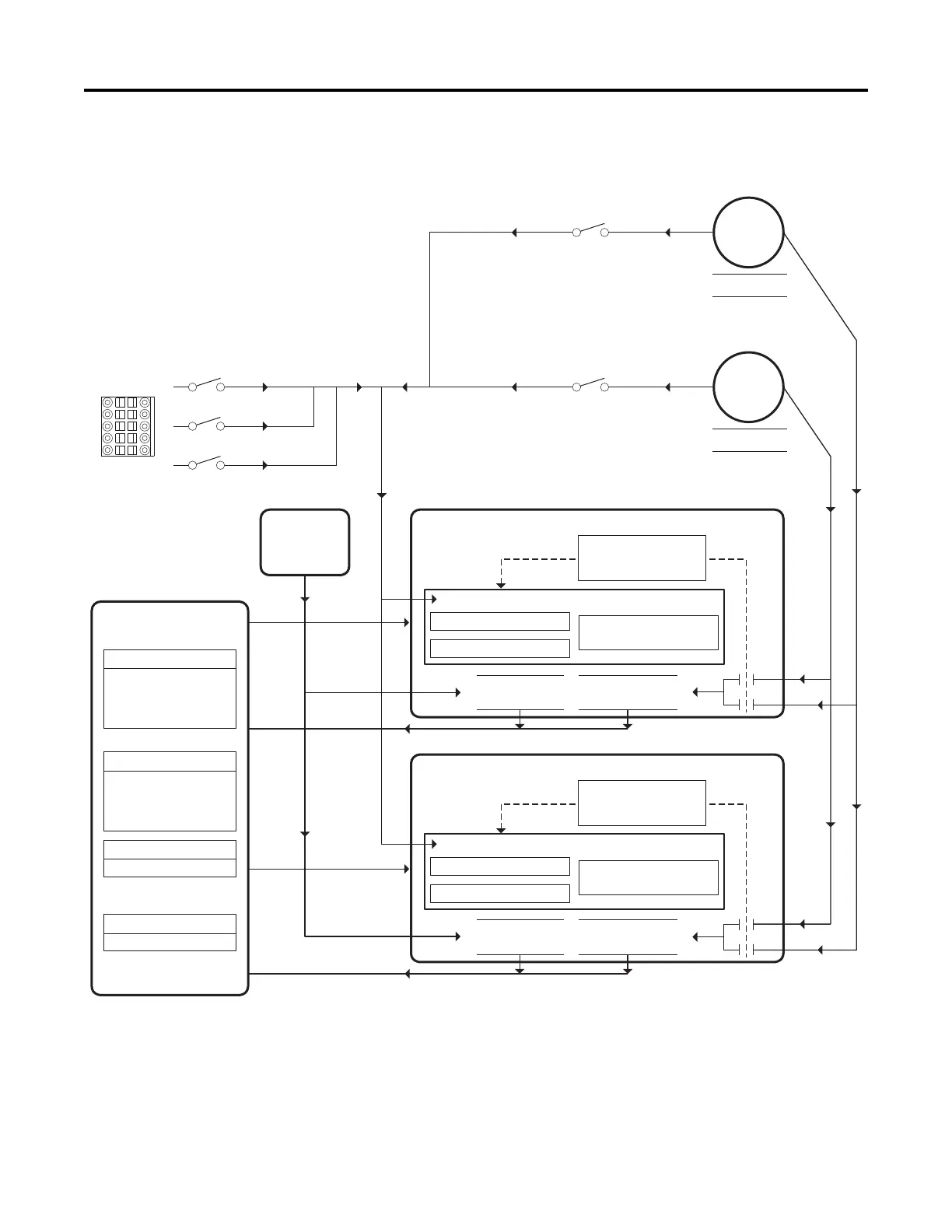
Device One
(Channel 1)
Feedback
Device Two
(Channel 2)
Position One
Position Two
Marker (Z) associated with channel.
Marker (Z) associated with channel.
Input
Input
Input
Switch 1, SW1
Switch 2, SW2
Home
Timer
(Cleared on
system event.)
Device Specification 0:
- Channel Select
- Rotation Select
Trigger Combination
Logic Config 0
Device Specification N:
- Channel Select
- Rotation Select
Trigger Combination
Logic Config N
Trigger Logic
Trigger Config 0 - Stage 1
Trigger Config 0 - Stage 2
Latched Time 0
(Output)
Latched Position 0
(Output)
Trigger Config N - Stage 1
Trigger Config N - Stage 2
Latched Time N
(Output)
Latched Position N
(Output)
Registration Latch 0
Registration Latch N
Trigger Logic
Option Bus I/O
Inputs
Bit pairs, 1 for each
registration latch:
- Arm
- Disarm
Bit pairs, 1 for each
registration latch:
- Armed
- Found
Registration Command
Registration Status
Latched Position 0
Latched Position 0
Latched Position 0
Latched Position 0
Not Shown:
Non-registration related data
 Loading...


