Rockwell Automation Publication 750-PM001N-EN-P - February 2017 485
Using DeviceLogix Appendix D
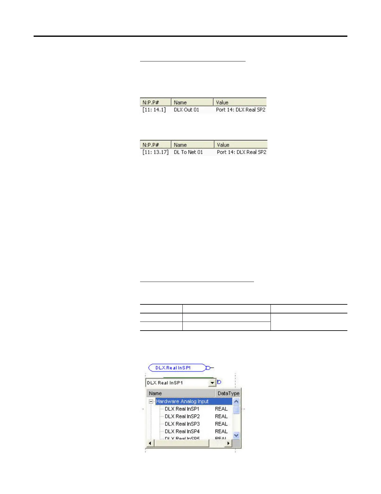
Example 2 – Writing data to the network
The DeviceLogix program controls an Analog Output value in DLX Out 01,
which is written to DLX Real SP2.
The DLX Real SP2 value is output to the network.
DLX Real SP2 is the intermediary register that allows the two Datalinks to work
together.
PowerFlex 753 (all) and PowerFlex 755 v2.xxx (and higher) Datalinks
and internal DeviceLogix scratchpad registers (P82…P105)
Each DLX In and DLX Out is a Datalink and cannot be directly mapped to each
other or another Datalink, such as a Datalink in the Port 13 Embedded
EtherNet/IP. Although the same method used with PowerFlex 755 v1.xxx
firmware can be employed, there is a more efficient method that does not require
a DeviceLogix Datalink to be used.
Example 1 – Reading data from the network
A value from the network is input to DLX Real InSP1.
DLX Real InSP1 can now be used as a Hardware Analog Input and used directly
with a Function Block (a DeviceLogix Datalink is not required).
Drive Datalink Value
753 Port 0 P895 [Data In A1] Port 14: DLX Real InSP1
755 Port 13 P1 [DL From Net 01]
 Loading...


