492 Rockwell Automation Publication 750-PM001N-EN-P - February 2017
Appendix D Using DeviceLogix
Example 4: Wet Well Operation
This example demonstrates how basic control logic can be used for simple
applications. It is assumed that the PowerFlex 755 has an I/O module installed in
Port 4.
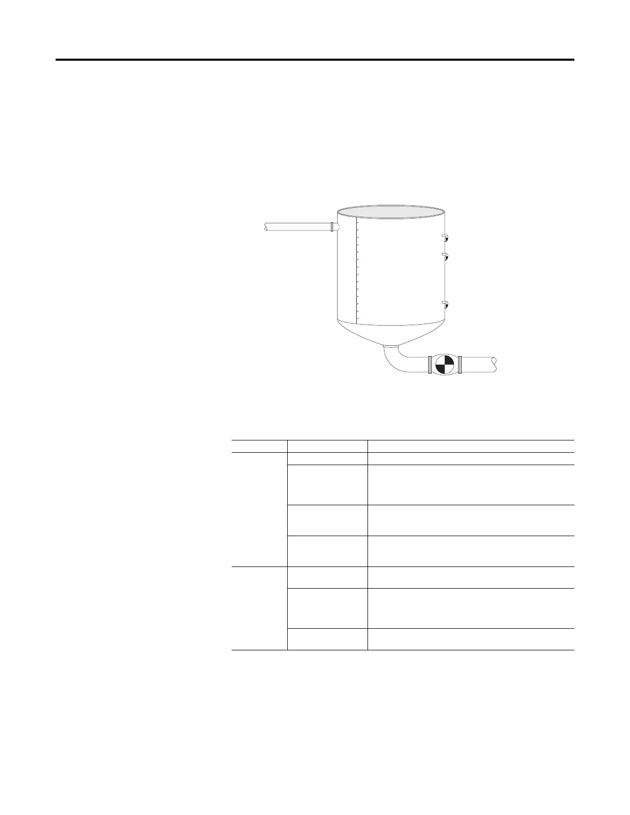
Figure 94 - Wet Well
The application consists of the following discrete I/O:
Type Name Description
Inputs Fault Reset pushbutton Used to reset any faults or alarms
Critical High-Level sensor Indicates a critically high level. It is normally a backup to the High-Level
sensor and is also used to detect if the High-Level sensor is faulty. When
ON, the drive operates at an even higher output frequency in case it is
due to a high inflow.
High-Level sensor Indicates the well is at a high level and it is time to start pumping
(normal operation). The drive operates at a ‘normal’ rate unless the
Critical High Level was reached.
Low-Level sensor When OFF, it is used to indicate that the well is empty (as long as the
High and Critical High-Level sensors are also OFF). The drive stops
operating (end of pumping cycle).
Outputs Sensor Fault pilot light Indicates that there is a problem with either the High-Level or Low-
Level sensors
Too Much Time Alarm pilot
light
If the drive operates for more than the normal amount of time it takes to
empty the well, there can be increased inflow or perhaps the Low-Level
sensor is stuck ON. An alarm indication is made and the drive continues
to operate.
Critical High-Fault flashing
light / alarm horn
Indicates a critically high level that requires immediate attention.
Outflow
Inflow
Critical High-Level Sensor
High-Level Sensor
Low-Level Sensor
 Loading...


