Rockwell Automation Publication 750-PM001N-EN-P - February 2017 75
Drive Port 0 Parameters Chapter 3
FEEDBACK & I/O
Digital Outputs
244 TO0 On Time
Transistor Output 0 On Time
Sets the “ON Delay” time for the digital outputs. This is the time between the occurrence
of a condition and activation of the relay or transistor.
Units:
Default:
Min/Max:
Secs
0
0 / 159999
RW 32-bit
Integer
245 TO0 Off Time
Transistor Output 0 Off Time
Sets the “OFF Delay” time for the digital outputs. This is the time between the
disappearance of a condition and de-activation of the relay or transistor.
Units:
Default:
Min/Max:
Secs
0.0
–/+1000000.0
RW Real
File
Group
No. Display Name
Full Name
Description
Values
Read-Write
Data Type
File
Group
No. Display Name
Full Name
Description
Values
Read-Write
Data Type
FEEDBACK & I/O
Motor PTC
250 PTC Cfg
Positive Temperature Coefficient Configuration
Sets the action that will be taken when the PTC is indicating over temperature.
“Ignore” (0) – No action is taken.
“Alarm” (1) – Type 1 alarm indicated.
“Flt Minor” (2) – Minor fault indicated. If running, drive continues to run.
Enable with P950 [Minor Flt Cfg]. If not enabled, acts like a major fault.
“FltCoastStop” (3) – Major fault indicated. Coast to Stop.
“Flt RampStop” (4) – Major fault indicated. Ramp to Stop.
“Flt CL Stop” (5) – Major fault indicated. Current Limit Stop.
Default:
Options:
0 – Ignore
0 – Ignore
1 – Alarm
2 Flt Minor
3 FltCoastStop
4 Flt RampStop
5 Flt CL Stop
RW 32-bit
Integer
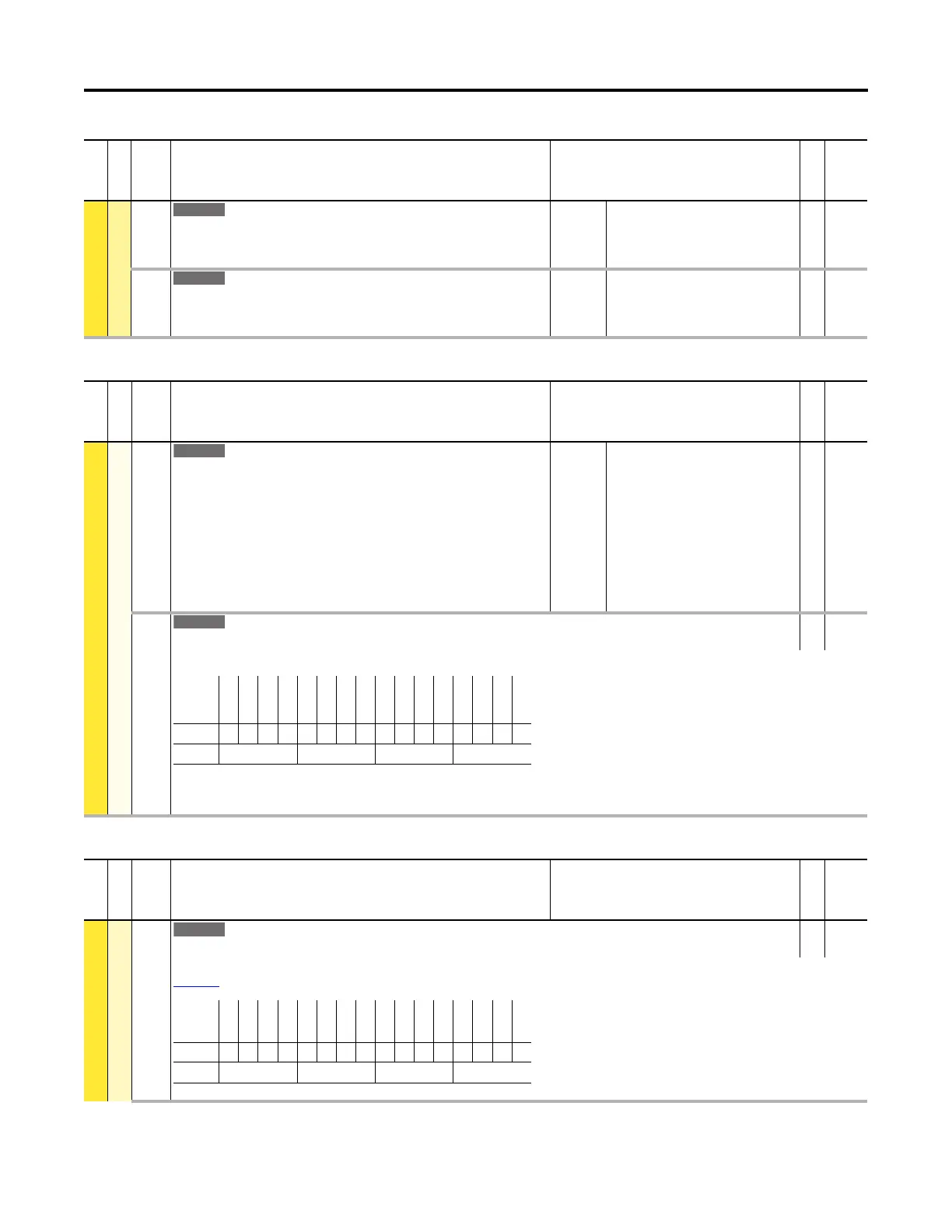
251 PTC Sts
Positive Temperature Coefficient Status
RO 16-bit
Integer
Status of the PTC.
Bit 0 “PTC Ok” – PTC is within the acceptable temperature range.
Bit 2 “Over Temp” – PTC is indicating over temperature
Options
Reserved
Reserved
Reserved
Reserved
Reserved
Reserved
Reserved
Reserved
Reserved
Reserved
Reserved
Reserved
Reserved
Over Temp
Reserved
PTC Ok
Default0000000000000000
Bit 1514131211109876543210
0 = Condition False
1 = Condition True
File
Group
No. Display Name
Full Name
Description
Values
Read-Write
Data Type
FEEDBACK & I/O
Analog Inputs
255 Anlg In Type
Analog Input Type
RO 16-bit
Integer
Status of the analog input mode set by Jumper J4 on the main control board. Refer to the PowerFlex 750-Series AC Drives Installation Instructions, publication
750-IN001
, for jumper locations and positions.
Options
Reserved
Reserved
Reserved
Reserved
Reserved
Reserved
Reserved
Reserved
Reserved
Reserved
Reserved
Reserved
Reserved
Reserved
Reserved
Analog
Default0000000000000000
Bit 1514131211109876543210
0 = Voltage Mode
1 = Current Mode
 Loading...


