12 Rockwell Automation Publication 750-UM003D-EN-P - March 2017
Chapter 1 Safety Concepts
Thermostat Trip
When the circuit is configured to trip with a thermostat, the ATEX option
module supports a normally closed, dry-contact thermostat. The safe-off
function initiates when the ATEX option module detects that the contact is
open. This trip can be the result of a broken wire, or an over-temperature
condition in the motor.
Positive Temperature Coefficient (PTC) Trip
When the circuit is configured to trip with a PTC-type thermal sensor, the
ATEX option module supports sensors with characteristics according to
DIN 44081/DIN 440. The ‘Mark A’ measuring circuit on the ATEX option
module is designed in accordance to IEC 60947-8 or EN 60947-8. This circuit
trips when the motor temperature has reached its trip point, or an open-wire/
short-circuit condition is detected in the sensor circuit.
Loss of voltage to the measuring circuit also initiates the safe-off function. The
ATEX option module internally sources this voltage.
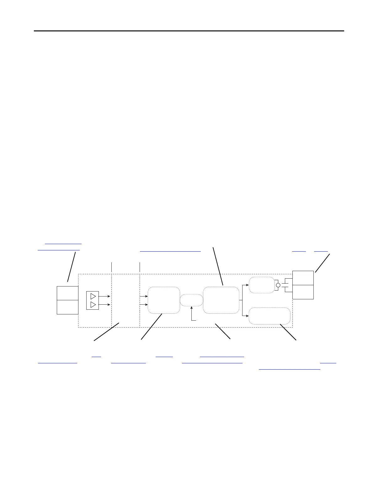
Figure 2 - ATEX Circuitry
Safe State
The safe state includes all operation that occurs outside of the other
monitoring and stopping behavior that is defined as part of the ATEX option
module. The ATEX safety function, as provided by the ATEX option module,
places the drive in a safe state by removing the power from the gate firing
circuits of the output power devices (IGBTs).
ATEX+
ATEX–
High Voltage
Possible
Isolation Safe Low Voltage
EnC
EnNOThermal
Sensor Type
Switch
Safety
Configuration
Switch
Latch
Relay Driver
Safe Shutdown
Signal
Reset Signal
Or
Field wiring to thermal sensor.
See Connect the Thermal
Sensor Wires on page 26.
Safety configuration switch to configure the
safety path for use with a safety option. See
Configure the Hardware on page 21.
Terminals EnC and EnNO must be wired correctly
when a safety option is present in the drive. See the
important statements on page 30 and page 31.
ATEX trip signals pass through an
isolation barrier to protect the drive
in a motor insulation fault. See ATEX
Monitoring on page 39.
Thermal sensor-type switch selects
between PTC and thermostatic-
type thermal sensors. See S1 Switch
Location on page 21.
An ATEX trip latches the drive into a
safe state until a reset sequence takes
place. See Restart the Drive after an
Over-temperature Fault on page41.
For installations that do not have the Safe
Torque Off or Safe Speed Monitor safety options
present, the ATEX safety function uses the
safety signal on the backplane. See Interface
Without a Safety Option on page 32.
 Loading...


