Rockwell Automation Publication 750-UM003D-EN-P - March 2017 25
Installation and Wiring Chapter 2
Configuration of the safety enable jumper on the main control board is a
requirement of each safety option module. For more information on these
requirements, see the specific option module user manual:
• PowerFlex Safe Torque Off User Manual, publication 750-UM002
• Safe Speed Monitor Option Module for PowerFlex 750-Series AC
Drives Safety Reference Manual, publication 750-RM001
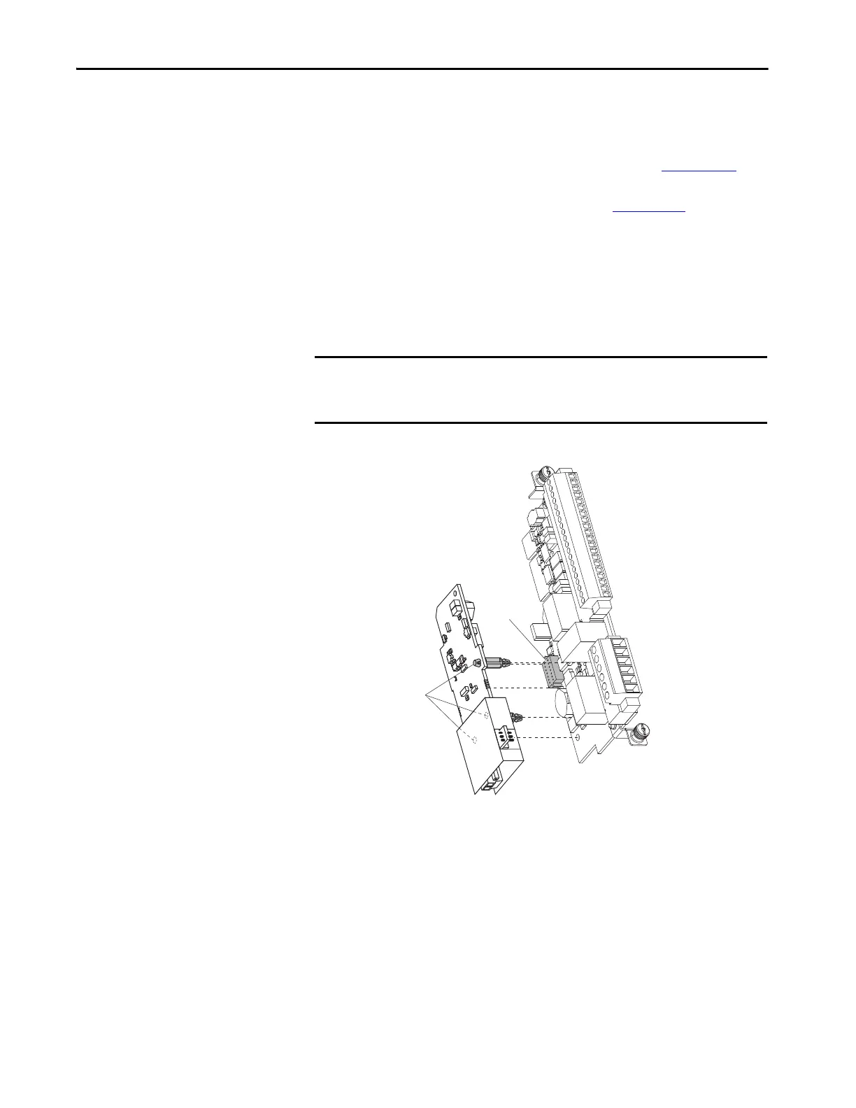
Assemble the ATEX and 11-Series I/O Option Modules
After the S1 switches and safety enable jumper are set for your application, join
the ATEX option module with the 11-Series I/O option module.
1. Align the stand-off pins and the 20-pin connector.
IMPORTANT Verify that the ATEX function switches are configured correctly for your
application before mounting on the 11-Series I/O option module. Once the
module is snapped into place, the switches are no longer accessible.
Stand-off Pins
20-pin
Connector
 Loading...


