Rockwell Automation Publication 520-UM001G-EN-E - September 2014 151
Troubleshooting Chapter 4
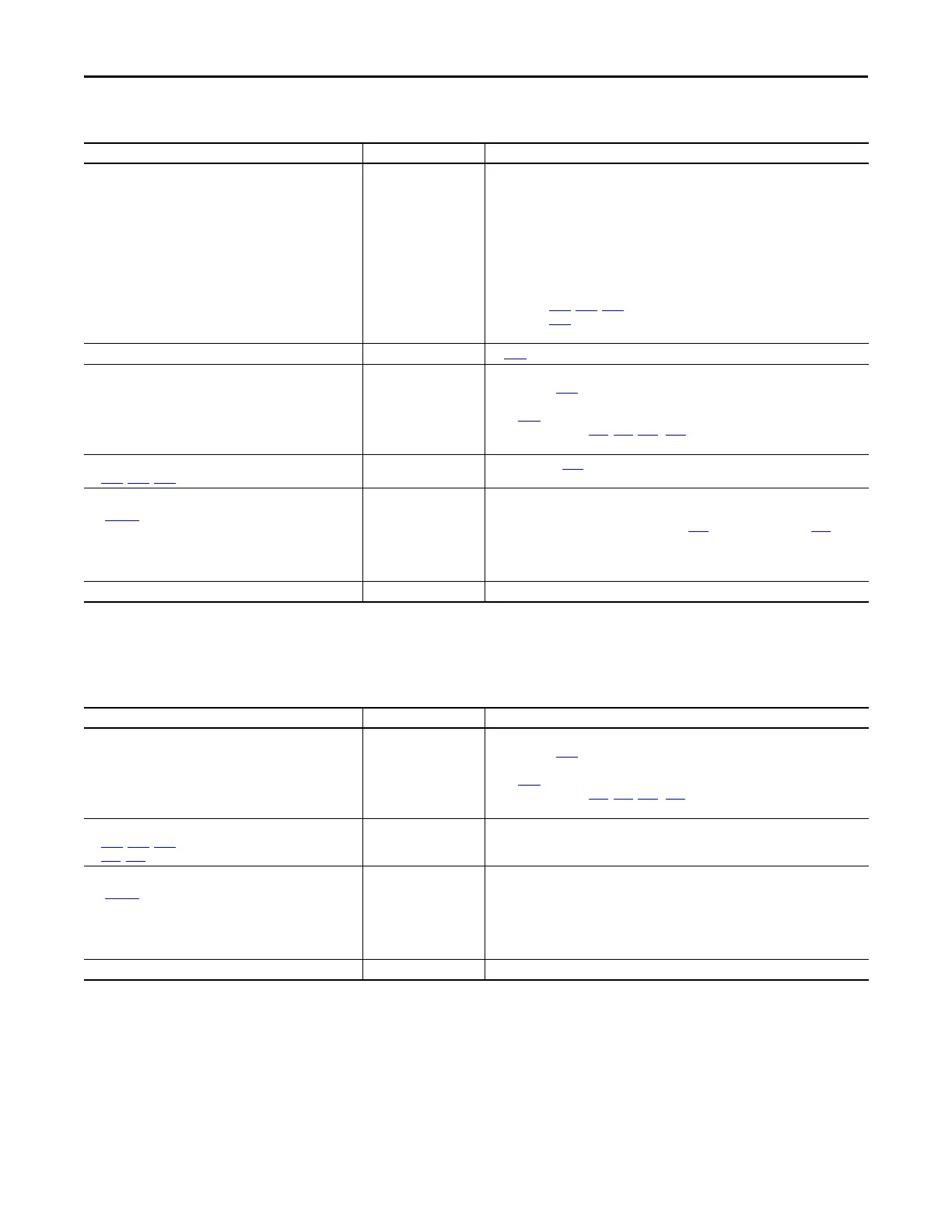
Motor does not Start.
Drive does not Start from Start or Run Inputs wired to the terminal
block.
Cause(s) Indication Corrective Action
No output voltage to the motor.
None
Check the power circuit.
• Check the supply voltage.
• Check all fuses and disconnects.
Check the motor.
• Verify that the motor is connected properly.
Check the control input signals.
• Verify that a Start signal is present. If 2-Wire control is used, verify that either the Run
Forward or Run Reverse signal is active, but not both.
• Verify that I/O Terminal 01 is active.
• Verify that P046
, P048, P050 [Start Source x] matches your configuration.
• Verify that A544 [Reverse Disable] is not prohibiting movement.
• Verify that safety inputs (Safety 1 and Safety 2) are active.
Improper boost setting at initial start-up. None Set A530 [Boost Select] to 2 “35.0, VT”.
Drive is Faulted Flashing red status light Clear fault.
• Press Stop if P045
[Stop Mode] is set to a value between “0” and “3”.
• Cycle drive power.
• Set A551 [Fault Clear] to 1 “Reset Fault” or 2 “Clear Buffer”.
• Cycle digital input if t062, t063, t065...t068 [DigIn TermBlk xx] is set to
13 “Clear Fault”.
Incorrect programming.
• P046
, P048, P050 [Start Source x] is set incorrectly.
None Check setting for b012 [Control Source].
Incorrect input wiring.
See page 42
for wiring examples.
• 2 wire control requires Run Forward, Run Reverse or Jog
input.
• 3 wire control requires Start and Stop inputs
• Stop input is always required.
None • Wire inputs correctly and/or install jumper.
• If the PowerFlex 525 Safe-Torque-Off function is used, verify that inputs are active.
• If 2-wire or 3-wire mode is used, verify that t062
[DigIn TermBlk 02] and t063 [DigIn
TermBlk 03] are set properly.
Incorrect Sink/Source jumper setting. None Set switch to match wiring scheme.
Cause(s) Indication Corrective Action
Drive is Faulted Flashing red status light Clear fault.
• Press Stop if P045
[Stop Mode] is set to a value between “0” and “3”.
• Cycle drive power.
• Set A551
[Fault Clear] to 1 “Reset Fault” or 2 “Clear Buffer”.
• Cycle digital input if t062, t063, t065...t068 [DigIn TermBlk xx] is set to
13 “Clear Fault”.
Incorrect programming.
• P046
, P048, P050 [Start Source x] is set incorrectly.
• t062, t063 [DigIn TermBlk 02/03] is set incorrectly.
None Check parameter settings.
Incorrect input wiring.
See page 42
for wiring examples.
• 2 wire control requires Run Forward, Run Reverse or Jog
input.
• 3 wire control requires Start and Stop inputs
• Stop input is always required.
None • Wire inputs correctly and/or install jumper.
• If the PowerFlex 525 Safe-Torque-Off function is used, verify that inputs are active.
Incorrect Sink/Source jumper setting. None Set switch to match wiring scheme.

 Loading...


