38 Rockwell Automation Publication 520-UM001G-EN-E - September 2014
Chapter 1 Installation/Wiring
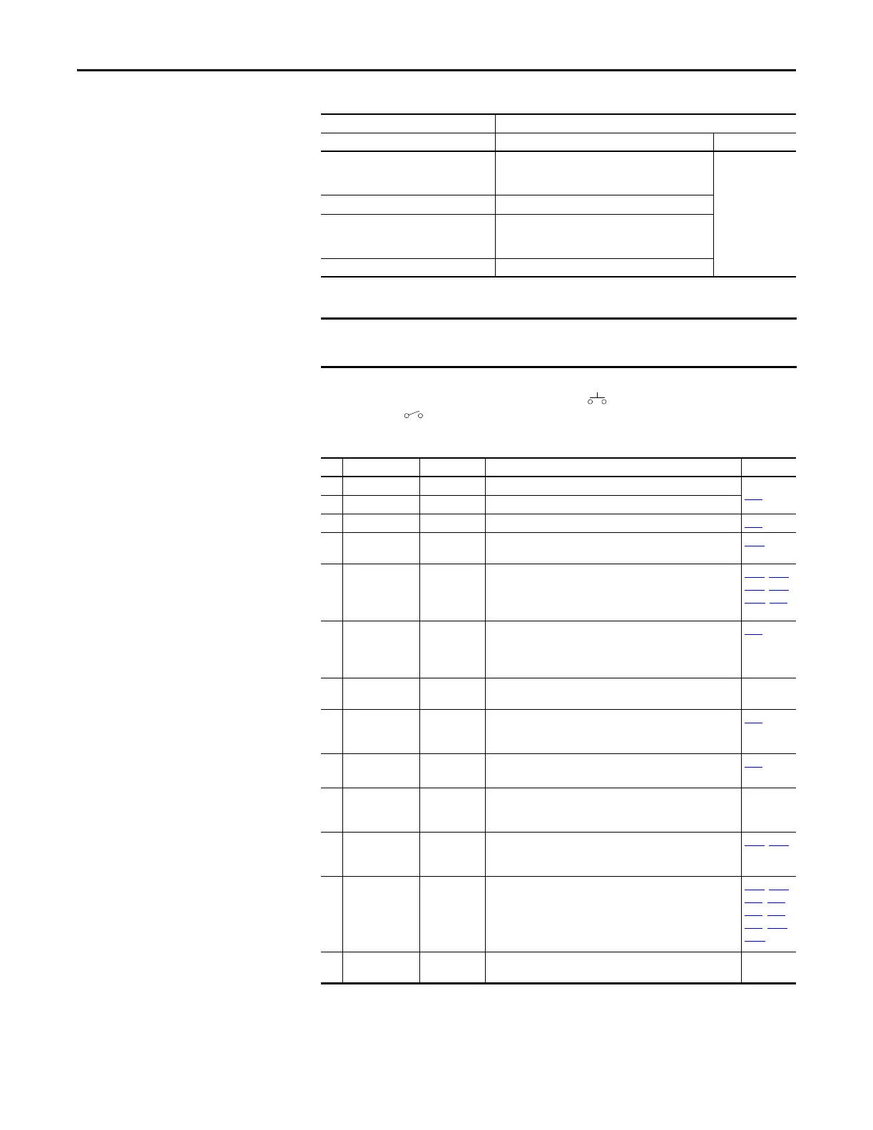
(2) Two wire control shown. For three wire control use a momentary input on I/O Terminal 02 to command a start. Use a
maintained input for I/O Terminal 03 to change direction.
Start Method Stop Method
t062, t063 [DigIn TermBlk xx] I/O Terminal 01 Stop Normal Stop
48 “2-Wire FWD” t064 [2-Wire Mode] is set to:
• 0, 1, or 2 = Coast
• 3 = per P045 [Stop Mode]
Per P045
[Stop Mode]
49 “3-Wire Start” Per P045 [Stop Mode]
50 “2-Wire REV” t064 [2-Wire Mode] is set to:
• 0, 1, or 2 = Coast
• 3 = per P045 [Stop Mode]
51 “3-Wire Dir” Per P045 [Stop Mode]
The drive is shipped with a jumper installed between I/O Terminals 01 and 11.
Remove this jumper when using I/O Terminal 01 as a stop or enable input.
Control I/O Terminal Designations
No. Signal Default Description Parameter
R1 Relay N.O. Fault Normally open contact for output relay.
t076
R2 Relay Common Fault Common for output relay.
R3 Relay N.C. Motor Running Normally closed contact for output relay. t081
01 Stop Coast Three wire stop. However, it functions as a stop under all input
modes and cannot be disabled.
P045
(2)
02 DigIn TermBlk 02/
Start/Run FWD
Run FWD Used to initiate motion and also can be used as a programmable
digital input. It can be programmed with t062 [DigIn TermBlk
02] as three wire (Start/Dir with Stop) or two wire (Run FWD/
Run REV) control. Current consumption is 6 mA.
P045, P046,
P048, P050,
A544, t062
03 DigIn TermBlk 03/
Dir/Run REV
Run REV Used to initiate motion and also can be used as a programmable
digital input. It can be programmed with t063 [DigIn TermBlk
03] as three wire (Start/Dir with Stop) or two wire (Run FWD/
Run REV) control. Current consumption is 6 mA.
t063
04 Digital Common – Return for digital I/O. Electrically isolated (along with the digital
I/O) from the rest of the drive.
–
05 DigIn TermBlk 05/
Pulse In
Preset Freq Program with t065 [DigIn TermBlk 05]. Also functions as a Pulse
Train input for reference or speed feedback. The maximum
frequency is 100 kHz. Current consumption is 6 mA.
t065
06 DigIn TermBlk 06 Preset Freq Program with t066 [DigIn TermBlk 06].
Current consumption is 6 mA.
t066
11 +24V DC – Referenced to Digital Common.
Drive supplied power for digital inputs.
Maximum output current is 100 mA.
–
12 +10V DC – Referenced to Analog Common.
Drive supplied power for 0...10V external potentiometer.
Maximum output current is 15 mA.
P047
, P049
13 0-10V In
(1)
Not Active For external 0-10V (unipolar) input supply or potentiometer
wiper.
Input impedance:
Voltage source = 100 kΩ
Allowable potentiometer resistance range = 1...10 kΩ
P047, P049,
t062, t063,
t065, t066,
t093, A459,
A471
14 Analog Common – Return for the analog I/O. Electrically isolated (along with the
analog I/O) from the rest of the drive.
–

 Loading...


