Rockwell Automation Publication 520-UM001G-EN-E - September 2014 39
Installation/Wiring Chapter 1
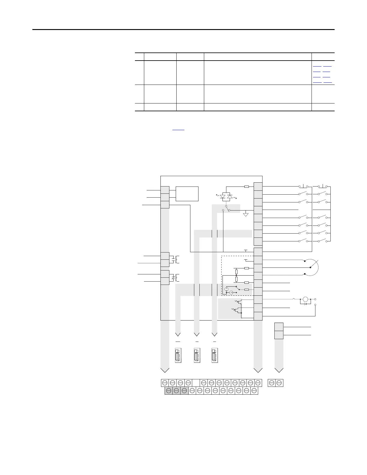
PowerFlex 525 Control I/O Terminal Block
PowerFlex 525 Control I/O Wiring Block Diagram
15 4-20mA In
(1)
Not Active For external 4-20 mA input supply.
Input impedance = 250 Ω
P047, P049,
t062, t063,
t065, t066,
A459, A471
C1 C1 – This terminal is tied to the RJ-45 port shield. Tie this terminal to
a clean ground in order to improve noise immunity when using
external communication peripherals.
–
C2 C2 – This is the signal common for the communication signals. –
(1) Only one analog frequency source may be connected at a time. If more than one reference is connected at the same time, an
undetermined frequency reference will result.
(2) See Footnote (1) on page 37
.
Control I/O Terminal Designations
No. Signal Default Description Parameter
04
05
06
07
01
02
03
08
11
12
13
14
15
16
17
18
19
Digital Common
DigIn TermBlk 05
DigIn TermBlk 06
DigIn TermBlk 07/Pulse
Stop
(1)
DigIn TermBlk 02/
Start/Run FWD
(2)
DigIn TermBlk 03/
Direction/Run REV
DigIn TermBlk 08
R1
R2
S1
S2
S+
Relay 1 N.O.
Relay 1 Common
+24V DC
+10V DC
0-10V (or ±10V) Input
Analog Common
4-20mA Input
Analog Output
Opto Output 1
Opto Output 2
RJ45 Shield
Comm Common
Opto Common
+24V
+10V
Safety 1
Safety 2
Safety +24V
Typical
SNK wiring
Typical
SRC wiring
R1
S1 S2 S+ 11 12 13 14 15 16 17 18 19
R2 R5 R6 01 02 03 04 05 06 07 08 C1 C2
30V DC
50 mA
Non-inductive
Common
24V
(3)
Pot must be
1...10 k ohm
2 W min.
0-10V
0/4-20 mA
SNK
Digital In
DigIn TermBlk 07 Sel
Analog Out
J10 J9 J5
Pulse In
SRCDigital
Input
0/4-20mA
0-10V
SRCSNK
R5
R6
Relay 2 Common
Relay 2 N.C.
C1
C2
Safe-Torque-O

 Loading...


