18 Rockwell Automation Publication 520-QS001A-EN-E - March 2014
PowerFlex 520-Series Adjustable Frequency AC Drive
Basic Display Group Parameters
See the PowerFlex 520-Series Adjustable Frequency AC Drive User Manual, publication 520-UM001 for detailed
descriptions of the parameters listed here, as well as the full list of available parameters.
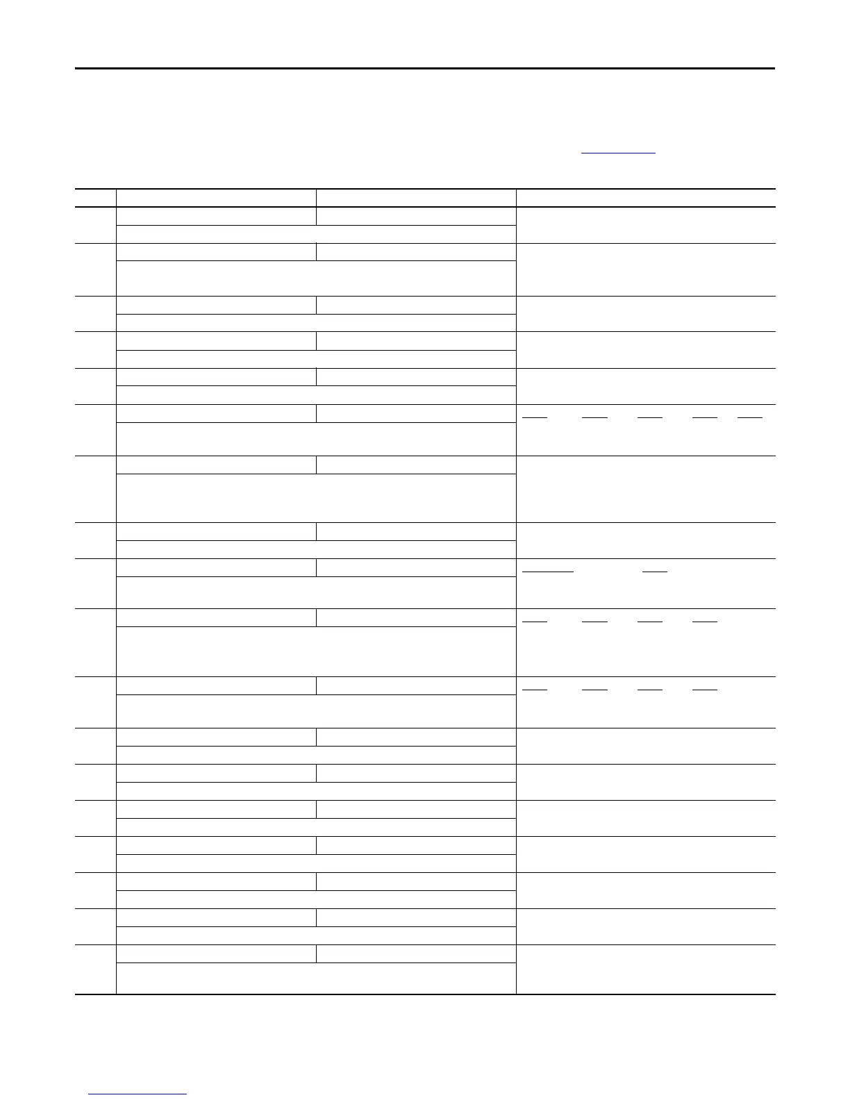
No. Parameter Min/Max Display/Options
b001 [Output Freq] 0.00/[Maximum Freq] 0.01 Hz
Output frequency present at T1, T2 & T3 (U, V & W). Does not include slip frequency.
b002 [Commanded Freq] 0.00/[Maximum Freq] 0.01 Hz
Value of the active frequency command even if the drive is not running.
Important: The frequency command can come from a number of sources.
b003 [Output Current] 0.00/(Drive Rated Amps x 2) 0.01 A
Output current present at T1, T2 & T3 (U, V & W).
b004 [Output Voltage] 0.0/Drive Rated Volts 0.1V
Output voltage present at T1, T2 & T3 (U, V & W).
b005 [DC Bus Voltage] 0/1200VDC 1VDC
Filtered DC bus voltage level of the drive.
b006 [Drive Status] 00000/11111 Digit 5
Digit 4 Digit 3 Digit 2 Digit 1
SafetyActive
(1)
Decelerating Accelerating Forward Running
Present operating condition of the drive.
(1) Setting is specific to PowerFlex 525 drives only.
b007,
b008,
b009
[Fault x Code] F0/F127 F0
A code that represents a drive fault. Codes appear in these parameters in the order they occur (b007
[Fault 1 Code] = the most recent fault). Repetitive faults are only recorded once.
See Fault and Diagnostic Group for more information.
b010 [Process Display] 0/9999 1
Output frequency scaled by [Process Disp Hi] and [Process Disp Lo].
b0012 [Control Source] 0000/2165 Digit 4, 3, & 2
Digit 1
Freq Command Source Start Command Source
Active source of the Start Command and Frequency Command. Normally defined by the settings of
P046, P048, P050 [Start Source x] and P047, P049, P051 [Speed Referencex].
b013 [Contrl In Status] 0000/1111 Digit 4
Digit 3 Digit 2 Digit 1
DB Trans On
(1)
DigIn TBlk 3 DigIn TBlk 2 DigIn TBlk 1
State of the digital terminal blocks 1...3 and DB transistor.
Important: Actual control commands may come from a source other than the control terminal block.
(1) Setting is specific to PowerFlex 525 drives only.
b014 [Dig In Status] 0000/1111 Digit 4 Digit 3 Digit 2 Digit 1
DigIn TBlk 8
(1)
DigIn TBlk 7
(1)
DigIn TBlk 6 DigIn TBlk 5
State of the programmable digital inputs.
(1) Setting is specific to PowerFlex 525 drives only.
b015 [Output RPM] 0/24000 rpm 1 rpm
Current output frequency in rpm. Scale is based on P035 [Motor NP Poles].
b016 [Output Speed] 0.0/100.0% 0.1%
Current output frequency in %. Scale is 0% at 0.00 Hz to 100% at P044 [Maximum Freq].
b017 [Output Power] 0.00/(Drive Rated Power x 2) 0.01 kW
Output power present at T1, T2 & T3 (U, V & W).
b018 [Power Saved] 0.00/655.35 kW 0.01 kW
Instantaneous power savings of using this drive compared to an across the line starter.
b019 [Elapsed Run time] 0/65535 x 10 hr 1 = 10 hr
Accumulated time drive is outputting power. Time is displayed in 10 hour increments.
b020 [Average Power] 0.00/(Drive Rated Power x 2) 0.01 kW
Average power used by the motor since the last reset of the meters.
b021 [Elapsed kWh] 0.0/100.0 kWh 0.1 kWh
Accumulated output energy of the drive. When the maximum value of this parameter is reached, it
resets to zero and b022 [Elapsed MWh] is incremented.

 Loading...


