26 Rockwell Automation Publication 520-QS001A-EN-E - March 2014
PowerFlex 520-Series Adjustable Frequency AC Drive
A498 [Motor Rr] 0.00/655.35 ohm 0.01 ohm Based on Drive Rating
Rotor resistance of induction motor.
A499 [Motor Lm] 0.0/6553.5 mH 0.1 mH Based on Drive Rating
Mutual Inductance of induction motor.
A500 [Motor Lx] 0.0/6553.5 mH 0.1 mH Based on Drive Rating
Leakage Inductance of induction motor.
A509 [Speed Reg Sel] 0/1 0 = “Automatic”
1 = “Manual”
0 = “Automatic”
Determines if PI gain of the “Vector” control mode speed regulator is set automatically or manually.
Parameters A521...A526 are set automatically by this parameter.
A510,
A512,
A514
[Freq x] 0.00/200.00% 0.01% Freq 1 = 8.33%
Freq 2 = 15.00%
Freq 3 = 20.00%
Sets the “Vector” control mode frequency.
A511,
A513,
A515
[Freq x BW] 0/40 Hz 1 Hz 10 Hz
Speed control loop bandwidth for “Vector” control mode.
A521,
A523,
A525
[Freq x Kp] 0.0/500.0% 0.1% 100.0%
Sets P-gain of “Vector” control mode when in frequency region 1, 2 or 3 for faster speed response during
dynamic-state where motor is still accelerating. If A509 [Speed Reg Sel] is set to 1 “Manual”, these
parameters can be changed.
A522,
A524,
A526
[Freq x Ki] 0.000/10.000 s 0.001 s 0.100 s
Sets I-gain of “Vector” control mode when in frequency region 1, 2 or 3 for faster speed response during
steady-state where motor is at its rated speed. If A509 [Speed Reg Sel] is set to 1 “Manual”, these
parameters can be changed.
A530 [Boost Select] 0/14 0 = “Custom V/Hz”
1 = “30.0, VT”
2 = “35.0, VT”
3 = “40.0, VT”
4 = “45.0, VT”
5 = “0.0, no IR”
6 = “0.0”
7 = “2.5, CT”
8 = “5.0, CT”
9 = “7.5, CT”
10 = “10.0, CT”
11 = “12.5, CT”
12 = “15.0, CT”
13 = “17.5, CT”
14 = “20.0, CT”
6 = “0.0” (For 400V and
600V drives, 5 HP and above)
7 = “2.5, CT” (For 200V
drives, 5 HP and above)
8 = “5.0, CT” (For drives
below 5 HP)
Sets the boost voltage (% of P031 [Motor NP Volts]) and redefines the V/Hz curve. Only used for V/Hz and
SVC control modes.
A531 [Start Boost] 0.0/25.0% 0.1% 2.5%
Sets the boost voltage (% of P031 [Motor NP Volts]) and redefines the V/Hz curve when A530 [Boost
Select] = 0 “Custom V/Hz” and P039 [Torque Perf Mode] = 0 “V/Hz”.
A532 [Break Voltage] 0.0/100.0% 0.1% 25.0%
Sets the voltage (in percent of [Base Frequency]) at the A533 [Break Frequency] if A530 [Boost Select] is
set to 0 “Custom V/Hz”.
A533 [Break Frequency] 0.0/500.0 Hz 0.1 Hz 15.0 Hz
Sets the frequency where A532 [Break Voltage] is applied if A530 [Boost Select] is set to 0 “Custom V/Hz”.
A534 [Maximum Voltage] Min = 10V AC (on 230V AC Drives); 20V AC (on 460V
AC Drives); 25V AC (on 600V AC Drives)
Max = 255V AC (on 230V AC Drives); 510V AC (on
460V AC Drives); 637.5V AC (on 600V AC Drives)
1V AC Drive Rated Volts
Sets the highest voltage the drive outputs.
= Stop drive before changing this parameter.
= Parameter is specific to PowerFlex 525 drives only.
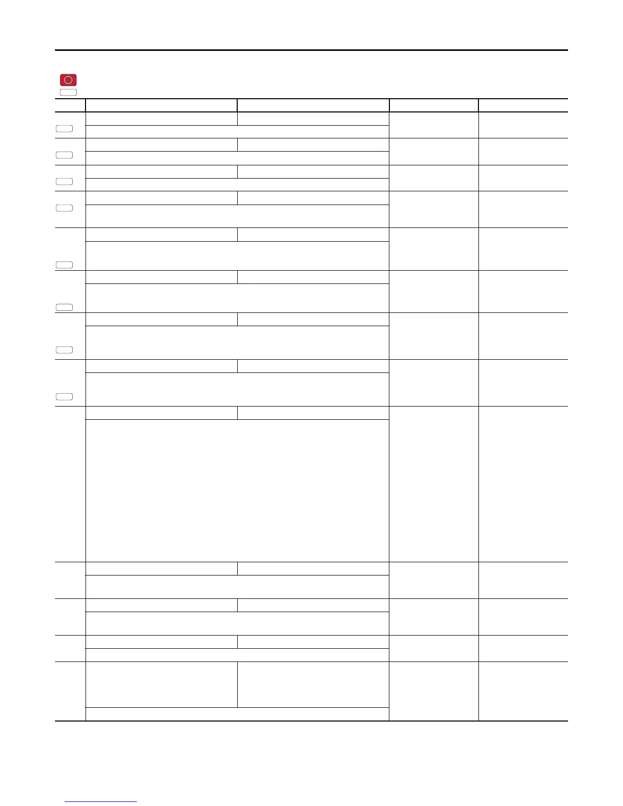
No. Parameter Min/Max Display/Options Default
PF 525

 Loading...


