28 Rockwell Automation Publication 520-QS001A-EN-E - March 2014
PowerFlex 520-Series Adjustable Frequency AC Drive
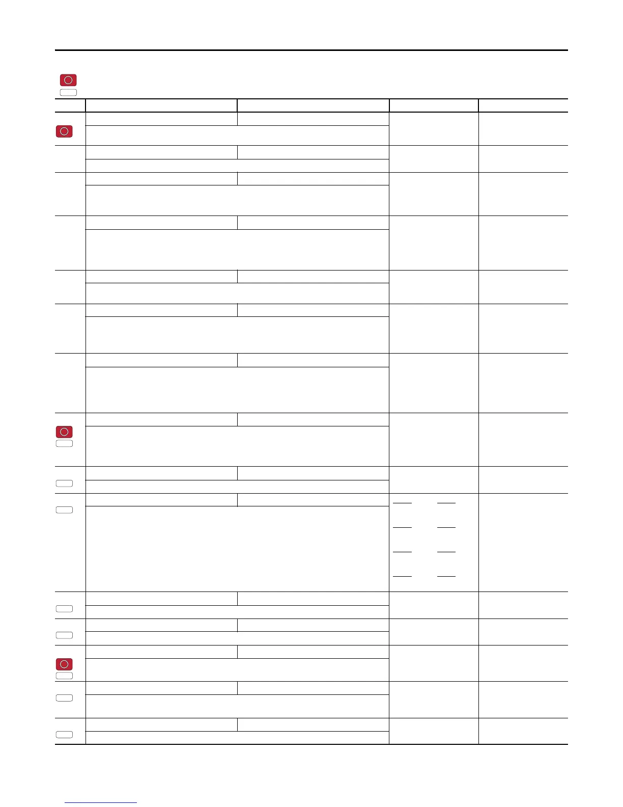
A551 [Fault Clear] 0/2 0 = “Ready/Idle”
1 = “Reset Fault”
2 = “Clear Buffer”
0 = “Ready/Idle”
Resets a fault and clears the fault queue.
A552 [Program Lock] 0000/9999 1111 0000
Protects parameters against change by unauthorized personnel with a 4-digit password.
A553 [Program Lock Mod] 0/3 0 = “Full Lock”
1 = “Keypad Lock”
2 = “Custom Only”
3 = “KeyPd Custom”
0 = “Full Lock”
Determines the lock mode used in parameter A552 [Program Lock]. When set to 2 or 3, A552 [Program
Lock] is added to the custom group to allow unlocking of parameters.
A554 [Drv Ambient Sel] 0/4 0 = “Normal”
1 = “55C”
2 = “60C”
3 = “65C +Fan Kit”
4 = “70C +Fan Kit”
0 = “Normal”
Sets the maximum expected ambient of the drive when used above 50 °C. When ambient temperature is
above 50 °C, the drive will apply necessary current derating.
A555 [Reset Meters] 0/2 0 = “Ready/Idle”
1 = “Reset Meters”
2 = “Reset Time”
0 = “Ready/Idle”
Resets the values stored in the parameters that track fault times and energy usage.
A556 [Text Scroll] 0/3 0 = “Off”
1 = “Low Speed”
2 = “Mid Speed”
3 = “High Speed”
2 = “Mid Speed”
Sets the scrolling speed of the text in the LCD display.
A557 [Out Phas Loss En] 0/1 0 = “Disabled”
1 = “Enabled”
0 = “Disabled”
Enable/disable output phase loss detection.
ATTENTION: Equipment damage and/or personal injury may result if this parameter is used in an
inappropriate application. Do not use this function without considering applicable local, national and
international codes, standards, regulations or industry guidelines.
A558 [Positioning Mode] 0/4 0 = “Time Steps”
1 = “Preset Input”
2 = “Step Logic”
3 = “Preset StpL”
4 = “StpLogic-Lst”
0 = “Time Steps”
Defines the positioning transition mode used for the position steps.
A559 [Counts Per Unit] 1/32000 1 4096
Sets the number of encoder counts equal to one user-defined unit.
A560 [Enh Control Word] 0000 0000/1111 1111 Digit 8
Digit 7
Logic In 2 Logic In 1
Digit 6
Digit 5
Traverse Dis Sync Enable
Digit 4
Digit 3
Pos Redefine Hold Step
Digit 2
Digit 1
Find Home Home Limit
0000 0000
Allows control of positioning and other functions through parameter control for use over comms. The
functions replicate the digital input options and function in the same way.
A561 [Home Save] 0/1 0 = “Home Reset”
1 = “Home Saved”
0 = “Home Reset”
Determines whether the current position is saved on power down.
A562 [Find Home Freq] 0.1/500.0 Hz 0.1 Hz 10.0 Hz
Sets the maximum frequency the drive uses when “Find Home” is issued.
A563 [Find Home Dir] 0/1 0 = “Forward”
1 = “Reverse”
0 = “Forward”
Sets the direction the drive commands when “Find Home” is issued.
A564 [Encoder Pos Tol] 1/50000 1 100
Sets the “At Position” and the “At Home’ tolerance around the encoder count. The value is added to and
subtracted from the target encoder unit value to create the tolerance range.
A565 [Pos Reg Filter] 0/15 1 8
Sets the error signal filter in the position regulator.
= Stop drive before changing this parameter.
= Parameter is specific to PowerFlex 525 drives only.
No. Parameter Min/Max Display/Options Default
PF 525

 Loading...


