24 Rockwell Automation Publication 520-QS001A-EN-E - March 2014
PowerFlex 520-Series Adjustable Frequency AC Drive
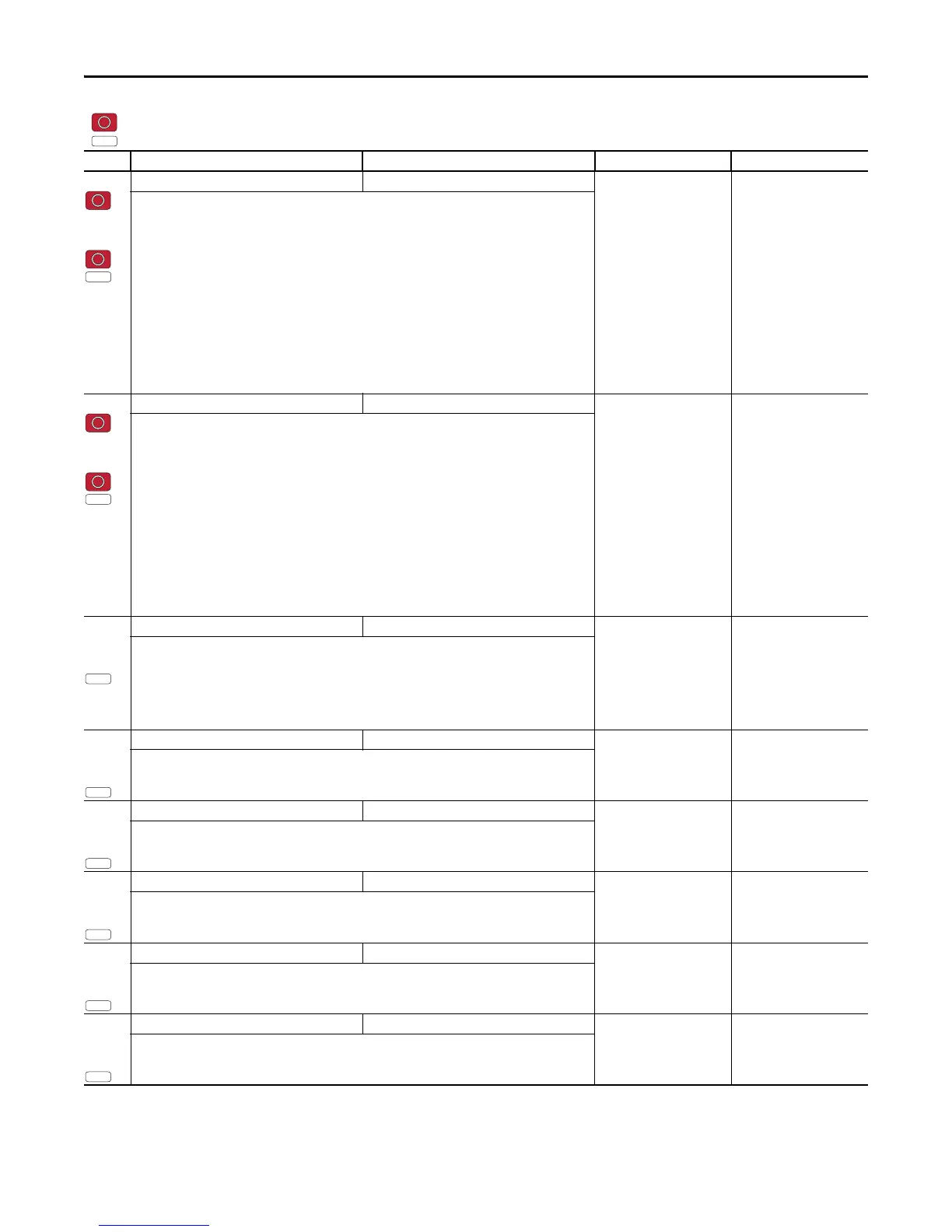
A458
A470
[PID x Trim Sel] 0/13 0 = “Disabled”
1 = “TrimOn Pot”
2 = “TrimOn Keypd”
3 = “TrimOn DSI”
4 = “TrimOn NetOp”
5 = “TrimOn 0-10V”
6 = “TrimOn 4-20”
7 = “TrimOn Prset”
8 = “TrimOn AnMlt”
(1)
9 = “TrimOn MOP”
10 = “TrimOn Pulse”
11 = “TrimOn Slgic”
(1)
12 = “TrimOn Encdr”
(1)
13 = “TrimOn ENet”
(1)
0 = “Disabled”
Sets the PID output as trim to the source reference.
(1) Setting is specific to PowerFlex 525 drives only.
A459
A471
[PID x Ref Sel] 0/13 0 = “PID Setpoint”
1 = “Drive Pot”
2 = “Keypad Freq”
3 = “Serial/DSI”
4 = “Network Opt”
5 = “0-10V Input”
6 = “4-20mA Input”
7 = “Preset Freq”
8 = “AnlgIn Multi”
(1)
9 = “MOP Freq”
10 = “Pulse Input”
11 = “Step Logic”
(1)
12 = “Encoder”
(1)
13 = “EtherNet/IP”
(1)
0 = “PID Setpoint”
Selects the source of the PID reference.
(1) Setting is specific to PowerFlex 525 drives only.
A460
A472
[PID x Fdback Sel] 0/6 0 = “0-10V Input”
1 = “4-20mA Input”
2 = “Serial/DSI”
3 = “Network Opt”
4 = “Pulse Input”
5 = “Encoder”
(1)
6 = “EtherNet/IP”
(1)
0 = “0-10V Input”
Selects the source of the PID feedback.
(1) Setting is specific to PowerFlex 525 drives only.
A461
A473
[PID x Prop Gain] 0.00/99.99 0.01 0.01
Sets the value for the PID proportional component when the PID mode is enabled.
A462
A474
[PID x Integ Time] 0.0/999.9 s 0.1 s 2.0 s
Sets the value for the PID integral component when PID mode is enabled.
A463
A475
[PID x Diff Rate] 0.00/99.99 0.01 0.00
Sets the value (in 1/second) for the PID differential component when PID mode is enabled.
A464
A476
[PID x Setpoint] 0.0/100.0% 0.1% 0.0%
Provides an internal fixed value for process setpoint when PID mode is enabled.
A465
A477
[PID x Deadband] 0.0/10.0% 0.1% 0.0%
Sets the lower limit of the PID output.
= Stop drive before changing this parameter.
= Parameter is specific to PowerFlex 525 drives only.
No. Parameter Min/Max Display/Options Default
PF 525
 Loading...


