Rockwell Automation Publication 520-QS001A-EN-E - March 2014 25
PowerFlex 520-Series Adjustable Frequency AC Drive
A466
A478
[PID x Preload] 0.0/500.0 Hz 0.1 Hz 0.0 Hz
Sets the value used to preload the integral component on start or enable.
A467
A479
[PID x Invert Err] 0/1 0 = “Normal”
1 = “Inverted”
0 = “Normal”
Changes the sign of the PID error.
A481 [Process Disp Lo] 0.00/99.99 0.01 0.00
Sets the value displayed in b010 [Process Display] when the drive is running at P043 [Minimum Freq].
A482 [Process Disp Hi] 0.00/99.99 0.01 0.00
Sets the value displayed in b010 [Process Display] when the drive is running at P044 [Maximum Freq].
A483 [Testpoint Sel] 0/FFFF 1 400
Used by Rockwell Automation field service personnel.
A484 [Current Limit 1] 0.0/Drive Rated Amps x 1.5 (Normal Duty); Drive
Rated Amps x 1.8 (Heavy Duty)
0.1 A Drive Rated Amps x 1.1
(Normal Duty); Drive Rated
Amps x 1.5 (Heavy Duty)
Maximum output current allowed before current limiting occurs.
A485 [Current Limit 2] 0.0/Drive Rated Amps x 1.5 (Normal Duty); Drive
Rated Amps x 1.8 (Heavy Duty)
0.1 A Drive Rated Amps x 1.1
Maximum output current allowed before current limiting occurs.
A486
A488
[Shear Pinx Level] 0.0/(Drive Rated Amps x 2) 0.1 A 0.0 A (Disabled)
Sets the value of current at which the shear pin fault occurs after the time set in A487, A489 [Shear Pin x
Time]. Setting the value at 0.0 A disables this function.
A487
A489
[Shear Pin x Time] 0.00/30.00 s 0.01 s 0.00 s
Sets the continuous time the drive must be at or above the value set in A486, A488 [Shear Pinx Level]
before a shear pin fault occurs.
A490 [Load Loss Level] 0.0/Drive Rated Amps 0.1 A 0.0 A
Provides a software trip (Load Loss fault) when the current drops below this level for the time specified in
A491 [Load Loss Time].
A491 [Load Loss Time] 0/9999 s 1 s 0 s
Sets the required time for the current to be below A490 [Load Loss Level] before a Load Loss fault occurs
A492 [Stall Fault Time] 0/5 0 = “60 Seconds”
1 = “120 Seconds”
2 = “240 Seconds”
3 = “360 Seconds”
4 = “480 Seconds”
5 = “Flt Disabled”
0 = “60 Seconds”
Sets the time that the drive remains in stall mode before a fault is issued.
A493 [Motor OL Select] 0/2 0 = “No Derate”
1 = “Min. Derate”
2 = “Max. Derate”
0 = “No Derate”
Drive provides Class 10 overload protection. Settings 0...2 select the derating factor for the I
2
t overload
function.
A494 [Motor OL Ret] 0/1 0 = “Reset”
1 = “Save”
0 = “Reset
Selects whether the motor overload counter is saved on power-down or reset on power-up.
A495 [Drive OL Mode] 0/3 0 = “Disabled”
1 = “Reduce CLim”
2 = “Reduce PWM”
3 = “Both-PWM 1st”
3 = “Both-PWM 1st”
Determines how the drive handles overload conditions that would otherwise cause the drive to fault.
A496 [IR Voltage Drop] 0.0/600.0VAC 0.1VAC Based on Drive Rating
Value of volts dropped across the resistance of the motor stator (autotune) for induction motor.
A497 [Flux Current Ref] 0.00/(Drive Rated Amps x 1.4) 0.01 A Based on Drive Rating
This is the current necessary for full motor flux. The value should be set to the full speed no-load current of
the motor.
= Stop drive before changing this parameter.
= Parameter is specific to PowerFlex 525 drives only.
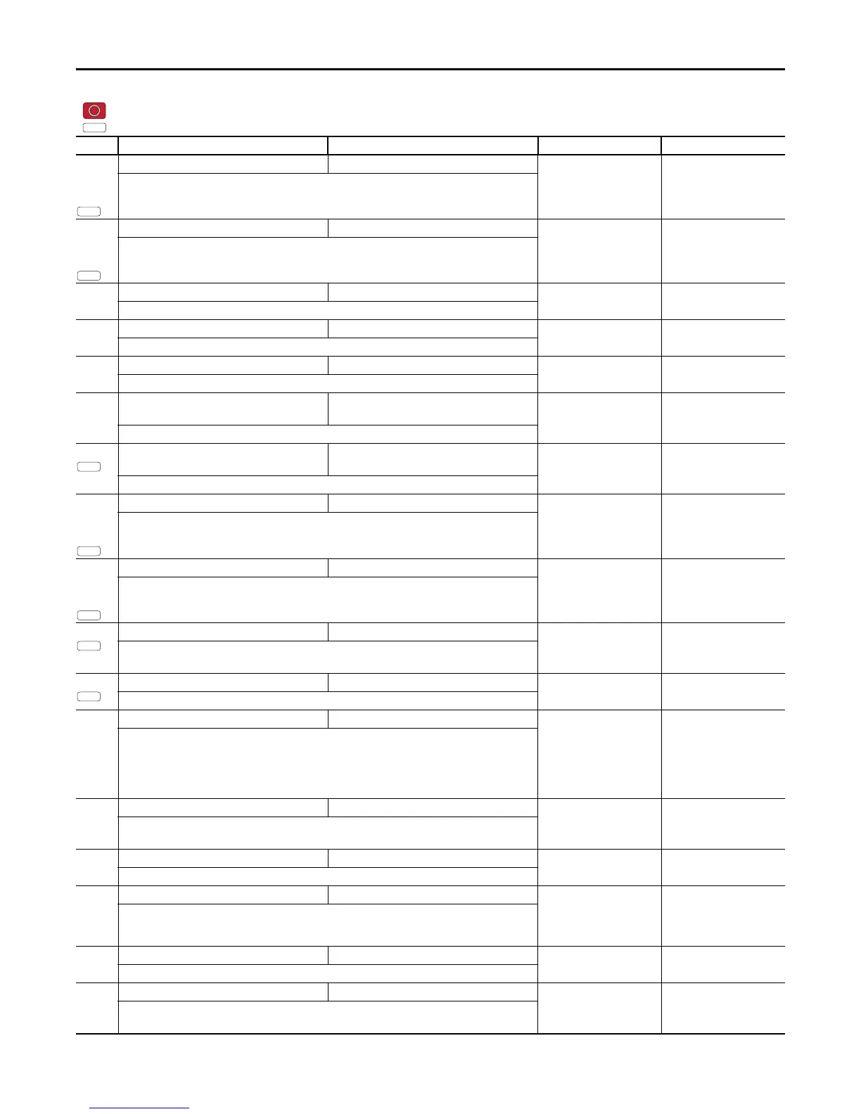
No. Parameter Min/Max Display/Options Default
PF 525
 Loading...


