Publication 20A-IN009C-EN-P
PowerFlex® 70 Adjustable Frequency AC Drive Installation Instructions 13
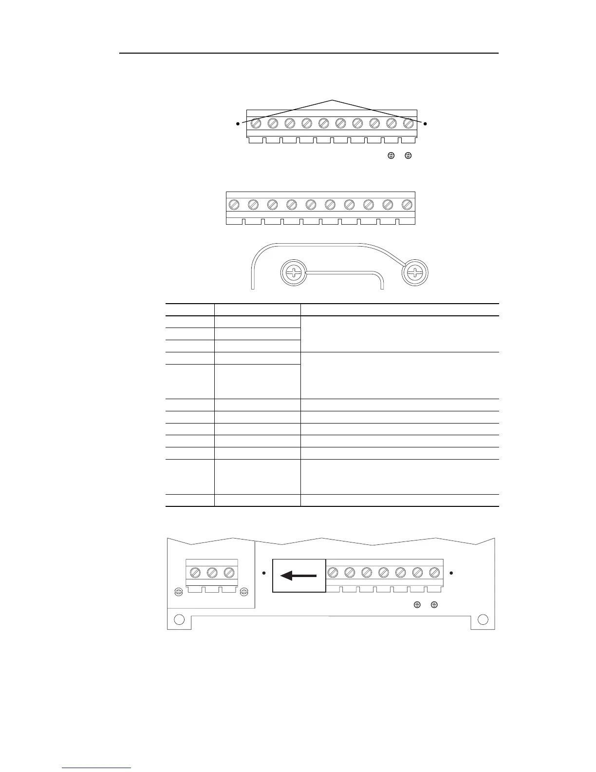
Figure 1 Frame A, B, C, D Power Terminal Block and DC Bus Test Points
Figure 2 Frame E Power Terminal Block
Figure 3 Power Input Terminals on Frame B with Internal RFI Filter Option
Terminal Description Notes
RR (L1)
3-Phase AC Line Input Power
For 1-Phase Input, connect to any two terminals.
SS (L2)
TT (L3)
BR1 DC Brake DB Resistor Connection - Important: Do not
connect both an internal and external DB resistor at
the same time. This may violate the minimum
allowed DB resistance and cause drive damage.
BR2 DC Brake
U U (T1) To Motor
V V (T2) To Motor
W W (T3) To Motor
PE PE Ground
PE PE Ground
-DC DC Bus (–)
➊ Test point on Frames A, B, C, and D located to
the left or right of the Power Terminal Block.
Frame E has a dedicated terminal.
+DC DC Bus (+)
L1
R
L2
S
L3
T
BR1
+DC
BR2
BRK
T1
U
T2
V
T3
W
PE PE
-DC
-DC
➊
L1
R
L2
S
L3
T
+DC –DC BR1 BR2 T1
U
T2
V
T3
W
PEPE
M6 M6
L1
R
L2
S
L3
T
BR1
+DC
BR2
BRK
T1
U
T2
V
T3
W
PE PE
-DC
-DC
L1
R
L2
S
L3
T

 Loading...


