EasyManuals Logo

Allen-Bradley PowerFlex 70 Installation Guide

Allen-Bradley PowerFlex 70
52 pages
To Next Page IconTo Next Page
To Previous Page IconTo Previous Page
Page #31 background imageLoading...
Page #31 background image
Publication 20A-IN009C-EN-P
PowerFlex® 70 Adjustable Frequency AC Drive Installation Instructions 31
By default, the user can program a digital input as an Enable input. The
status of this input is interpreted by drive software. If the application
requires the drive to be disabled without software interpretation, a
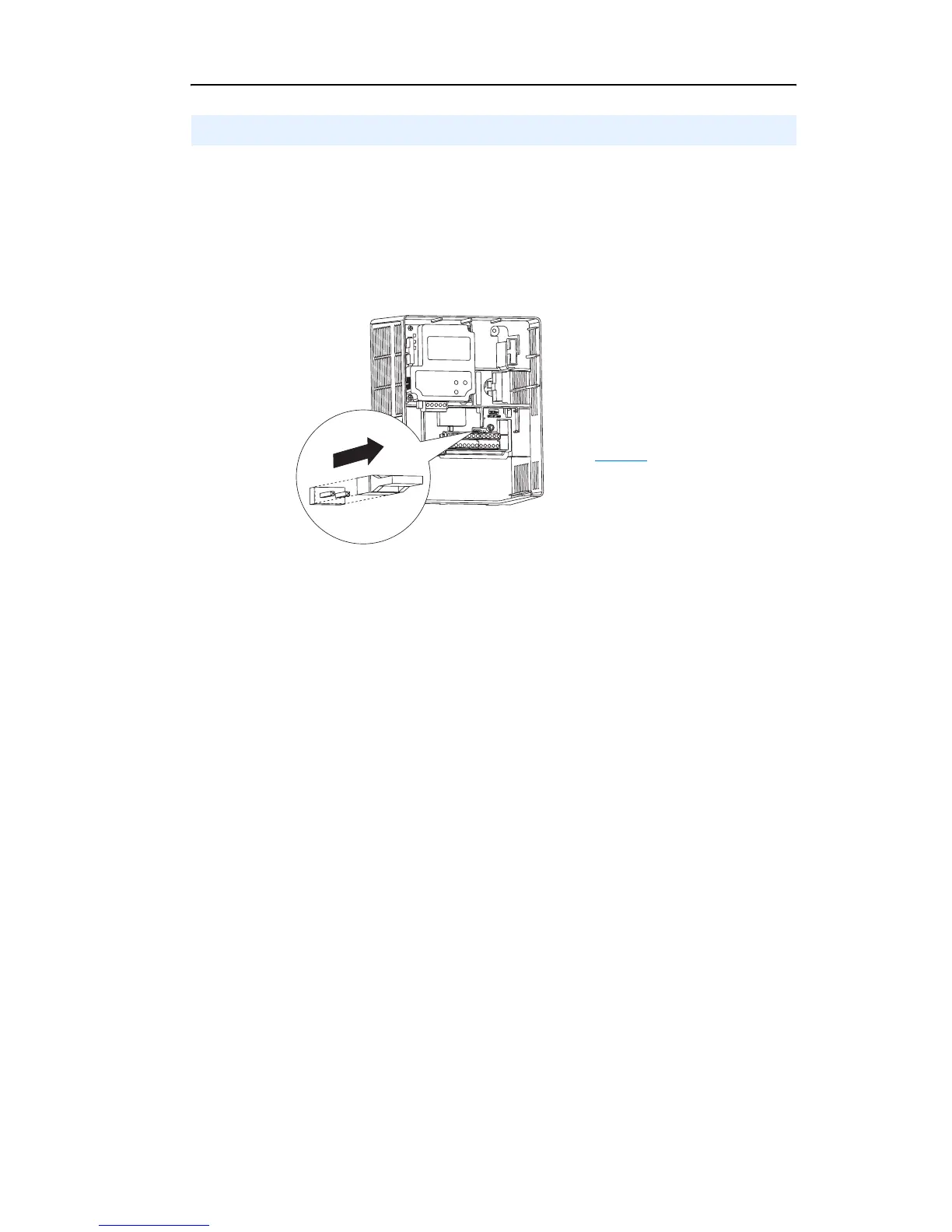
hardware enable configuration can be utilized. This is done by removing
the enable jumper (ENBL JMP) and wiring the enable input to “Digital
In 6” (see below).
1.Remove drive cover.
2.Locate and remove the Enable
Jumper on the Main Control
Board (see diagram).
3.Wire Enable to “Digital In 6”
(see Table J
).
Hardware Enable Circuitry (Enhanced Control Only)

Other manuals for Allen-Bradley PowerFlex 70

Questions and Answers:

Question and Answer IconNeed help?

Do you have a question about the Allen-Bradley PowerFlex 70 and is the answer not in the manual?

Allen-Bradley PowerFlex 70 Specifications

General IconGeneral
Input Voltage200-240V AC, 380-480V AC, 500-600V AC
Frequency Range0 - 400 Hz
Humidity5% to 95% non-condensing
Output Voltage0 to Input Voltage
Control MethodsSensorless Vector Control
CommunicationsEthernet/IP, DeviceNet, ControlNet
Protection FeaturesOvercurrent, Overvoltage, Undervoltage, Overtemperature, Ground Fault
Operating Temperature0°C to 50°C (32°F to 122°F)
Storage Temperature-40°C to 70°C (-40°F to 158°F)
Enclosure RatingIP20, NEMA Type 1

Related product manuals