Publication 20A-IN009C-EN-P
30 PowerFlex® 70 Adjustable Frequency AC Drive Installation Instructions
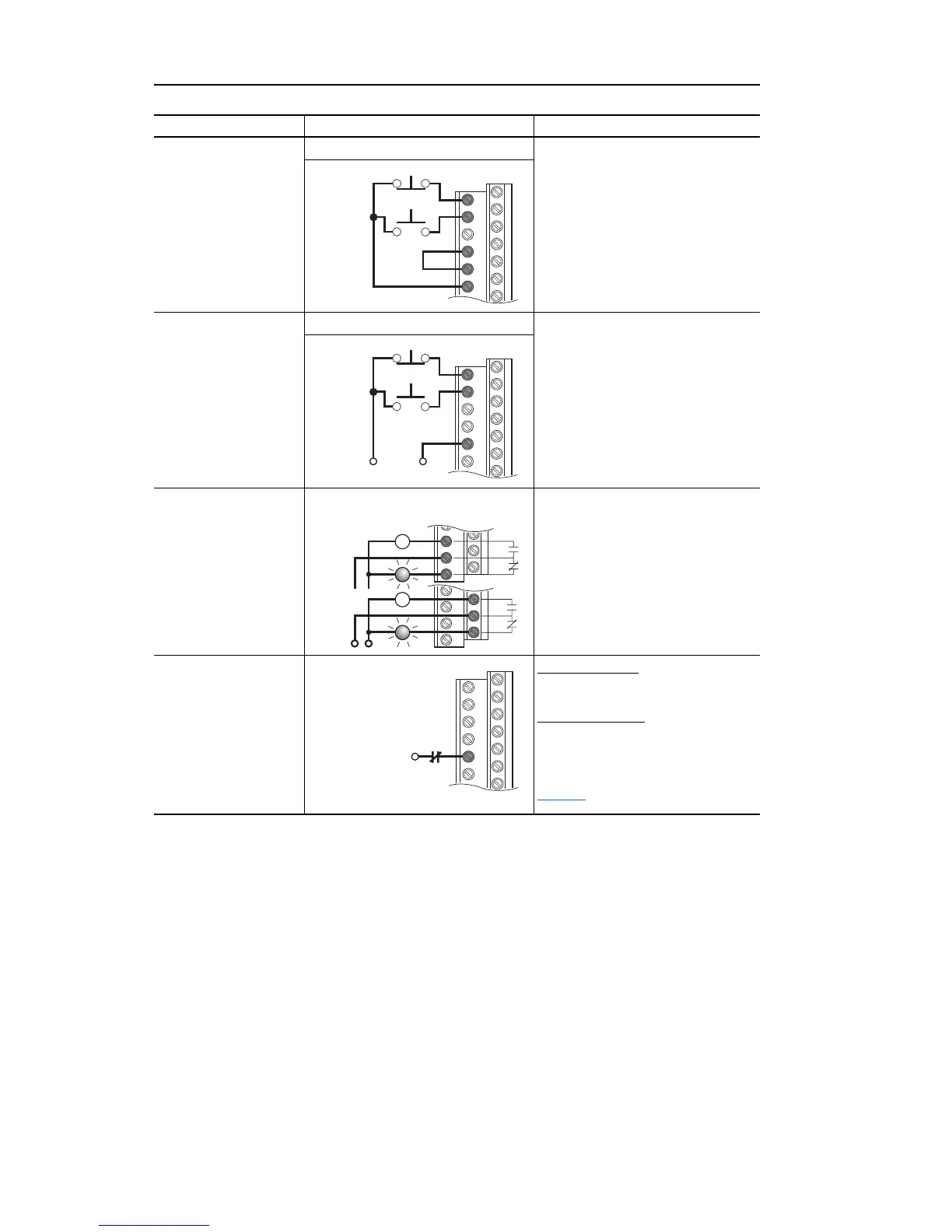
3 Wire
(1)
Control Internal Supply Use factory default parameter
settings.
Digital Input 1:
Param. 361 = 4 “Stop – CF”
Digital Input 2:
Param. 362 = 5 “Start”
3 Wire
(1)
Control External Supply Use factory default parameter
settings.
Digital Input 1:
Param. 361 = 4 “Stop – CF”
Digital Input 2:
Param. 362 = 5 “Start”
Digital Output
Form C Relays
Energized in Normal
State.
Select Source:
Use factory default parameter
settings.
Digital Out1 Sel:
Param. 380 = 1 “Fault”
Digital Out2 Sel:
Param. 384 = 4 “Run”
Enable Input
Shown in enabled state.
Standard Control
Param. 366 = 1 “Enable”
Enhanced Control
Param. 366 = 1 “Enable”
For dedicated hardware Enable:
Remove Enable Jumper (see
page 31
)
(1) Digital inputs can be wired for 2 Wire or 3 Wire Start/Stop control. Three Wire control requires
separate Start and Stop signals. Two Wire control requires only one input signal configured
Run-Hi/Stop-Lo.
Input/Output Connection Example Required Parameter Settings
1
2
7
8
9
Stop
Start
+24V Common
1
2
8
Stop
Start
11
12
13
24
25
26
Power
Source
or
6

 Loading...


