PowerFlex 700 Technical Data
20B-TD001F-EN-P 53
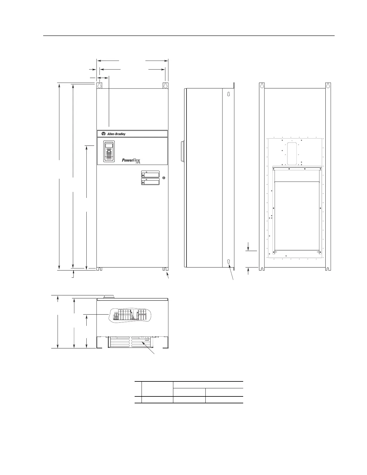
Frame 5 NEMA/UL Type 12 Stand-alone – 400…690V Only
Dimensions are in millimeters and (inches)
Frame
Description
Approx. Weight
(1)
kg (lbs.)
(1)
Weights include HIM and Standard I/O.
Drive Drive & Packaging
5 Stand-alone 102.51 (226.0) 154.68 (341.0)
609.6 (24.00)
25.4 (1.00)
105.5 (4.15)
1574.8
(62.00)
1061.5
(41.79)
16.8 (0.66)
1543.0 ±1.5
(62.75 ±0.06)
450.7
(17.75) Max.
425.5
(16.75)
287.0
(11.30)
Air Inlet
558.8 (22.00)
REMOTE SOURCE(S) OF POWER.
DISCONNECT ALL SOURCES OF POWER
BEFORE OPENING THE DOOR.
DANGER
DANGER
ELECTRICAL SHOCK HAZARD FROM
ENERGY STORAGE CAPACITORS.
VERIFY LOW VOLTAGE DISCHARGE
BEFORE SERVICING.
SEE INSTRUCTION MANUAL.
13.5 (0.53) Dia.
4 Places (See Note A)
12.7 (0.50) Dia.
Lifting Holes
140.0
(5.51)
Air
Outlet
Note A:
Mount with 0.50 Inch UNC Grade 5 or Higher Screws
or
M12 Material Class 5.6 or Higher Screws
Use Flat Washer with each Fastener

 Loading...


