PowerFlex 700 Technical Data
20B-TD001F-EN-P 73
Environment
(continued)
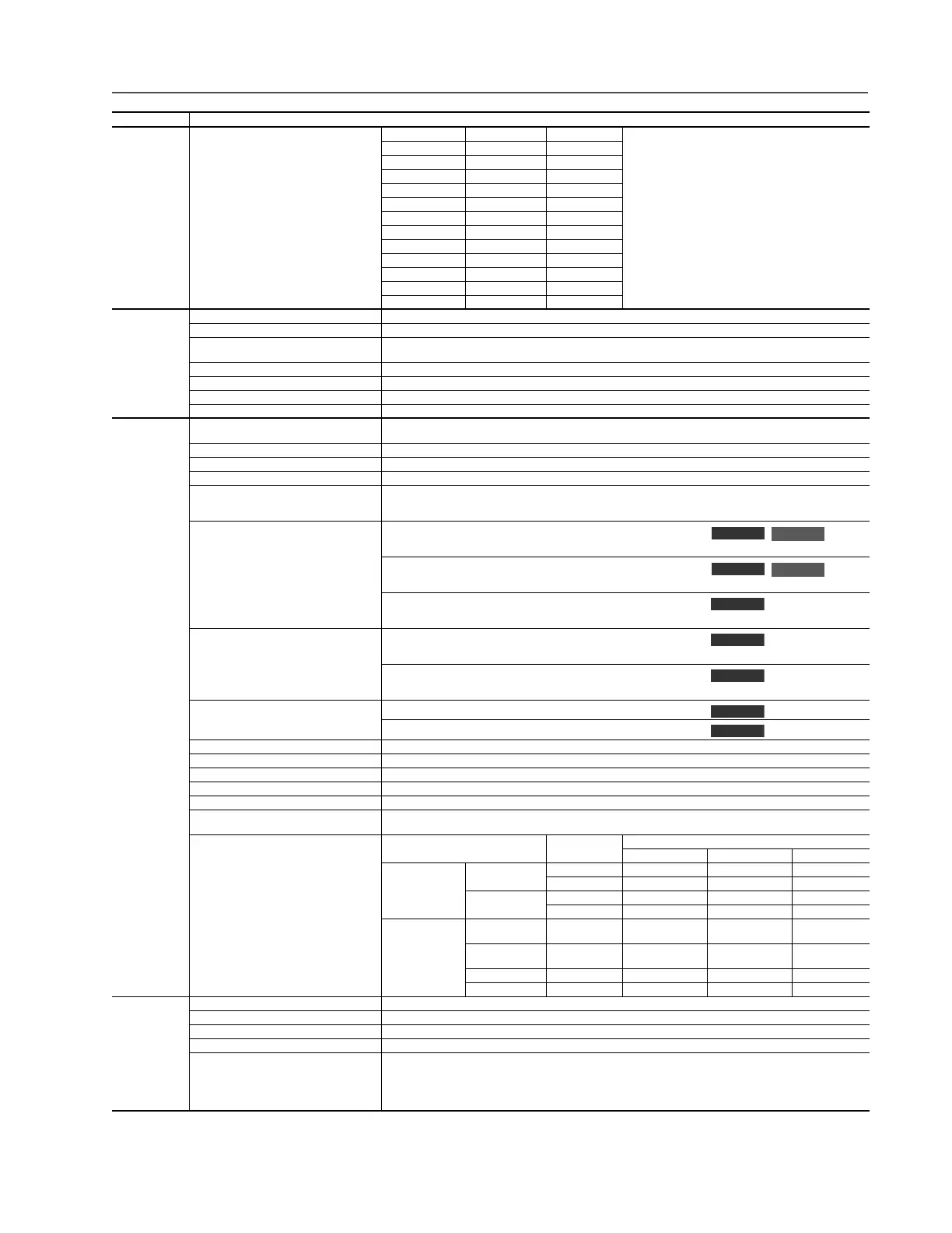
Sound: Frame Fan Speed Sound Level
Note: Sound pressure level is measured at 2 meters.
0 30 CFM 58 dB
1 30 CFM 59 dB
2 50 CFM 57 dB
3 120 CFM 61 dB
4 190 CFM 59 dB
5 200 CFM 71 dB
6 300 CFM 72 dB
7 756 CFM 74 dB
8 1200 CFM 78 dB
9 2800 CFM 82 dB
10 Inverter 1850 CFM 78 dB
10 Converter 1200 CFM 78 dB
Electrical Voltage Tolerance: See page 75 for full power and operating range.
Input Frequency Tolerance: 47…63 Hz.
Input Phases: Three-phase input provides full rating for all drives. Single-phase operation provides 50% of rated current (see page 32).
Frames 0…7: The drive can be supplied as 6 pulse or 18 pulse in an engineered package.
Displacement Power Factor: 0.98 across entire speed range.
Efficiency: 97.5% at rated amps, nominal line volts.
Maximum Short Circuit Rating: 200,000 Amps symmetrical.
Actual Short Circuit Rating: Determined by AIC rating of installed fuse/circuit breaker.
Control Method: Sine coded PWM with programmable carrier frequency. Ratings apply to all drives (refer to the Derating Guidelines in the PowerFlex
Reference Manual). The drive can be supplied as 6 pulse or 18 pulse in a configured package.
Carrier Frequency: 2, 4, 8 & 10 kHz. Drive rating based on 4 kHz (see pages 33 through 39 for exceptions).
Output Voltage Range: 0 to rated motor voltage
Output Frequency Range: Standard Control – 0 to 400 Hz., Vector Control – 0 to 420 Hz
Frequency Accuracy
Digital Input:
Analog Input:
Within ±0.01% of set output frequency.
Within ±0.4% of maximum output frequency.
Frequency Control: Speed Regulation - w/Slip Compensation (Volts per Hertz Mode)
0.5% of base speed across 40:1 speed range, 40:1 operating range
10 rad/sec bandwidth
Speed Regulation - w/Slip Compensation (Sensorless Vector Mode)
0.5% of base speed across 80:1 speed range, 80:1 operating range
20 rad/sec bandwidth
Speed Regulation - w/Feedback (Sensorless Vector Mode)
0.1% of base speed across 80:1 speed range, 80:1 operating range
20 rad/sec bandwidth
Speed Control: Speed Regulation - w/o Feedback (Vector Control Mode)
0.1% of base speed across 120:1 speed range, 120:1 operating range
50 rad/sec bandwidth
Speed Regulation - w/Feedback (Vector Control Mode)
0.001% of base speed across 120:1 speed range, 1000:1 operating range
250 rad/sec bandwidth
Torque Regulation: Torque Regulation - w/o Feedback ±5%, 600 rad/sec bandwidth
Torque Regulation - w/Feedback ±2%, 2500 rad/sec bandwidth
Selectable Motor Control: Sensorless Vector with full tuning. Standard V/Hz with full custom capability. PF700 adds Vector Control.
Stop Modes: Multiple programmable stop modes including - Ramp, Coast, DC-Brake, Ramp-to-Hold and S-curve.
Accel/Decel: Two independently programmable accel and decel times. Each time may be programmed from 0…3600 seconds in 0.1 second increments.
Intermittent Overload: 110% Overload capability for up to 1 minute, 150% Overload capability for up to 3 seconds
Current Limit Capability: Proactive Current Limit programmable from 20…160% of rated output current. Independently programmable proportional & integral gain.
Electronic Motor Overload Protection: Class 10 protection with speed sensitive response. Investigated by U.L. to comply with N.E.C. Article 430. U.L. File E59272, volume
12.
Digital/Analog Input Latency
Signal Motor Control
Latency
Min. Max Typical
Digital Input Start FVC 8.4 ms 10.4 ms 8.4 ms
SVC 9.2 ms 16.0 ms 9.2 ms
Stop FVC 10.0 ms 12.4 ms 10.4 ms
SVC 10.0 ms 12.0 ms 10.4 ms
Analog Input Torque
(at 4 kHz PWM)
FVC 772 μs 1.06 ms 840 μs
To rq u e
(at 2 kHz PWM)
FVC 1.008 ms 1.46 ms 1.256 ms
Speed FVC 4.6 ms 8.6 ms 4.8 ms
Speed SVC 4.8 ms 12.4 ms 6.4 ms
Encoder Type: Incremental, dual channel
Supply: 12V, 250 mA. 12V, 10 mA minimum inputs isolated with differential transmitter, 250 kHz maximum.
Quadrature: 90°, ±27 degrees at 25 degrees C.
Duty Cycle: 50%, +10%
Requirements: Encoders must be line driver type, quadrature (dual channel) or pulse (single channel), 8…15V DC output (4…6V DC when jumpers
are in 5V position), single-ended or differential and capable of supplying a minimum of 10 mA per channel. Maximum input frequency
is 250 kHz. The Encoder Interface Board accepts 12V DC square-wave with a minimum high state voltage of 7.0V DC. With the
jumpers in the 5V position, the encoder will accept a 5V DC square-wave with a minimum high state voltage of 3.0V DC. In either
jumper position, the maximum low state voltage is 0.4V DC.
Category Specification
Standard
Vector
Standard
Vector
Vector
Vector
Vector
Vector
Vector

 Loading...


