f9
f11
f10
f12
g
h
i
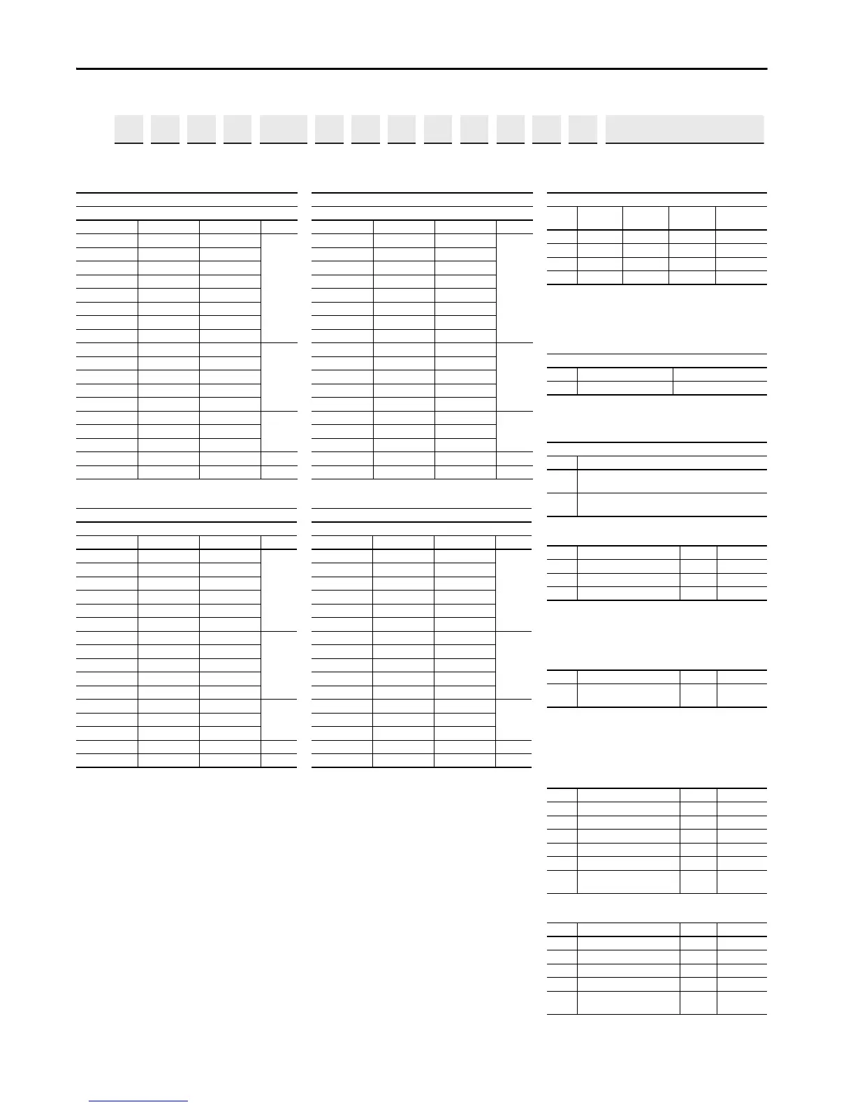
20G Control Options Selection
20J Control Options Selection
20G Power Options Selection
20J Power Options Selection
PowerFlex 755TM Common Bus Inverter ND Rating
400V, 50 Hz Input
Code Amps kW Frame
302 302 160
8
367 367 200
460 460 250
540 540 315
585 585 315
650 650 355
750 750 400
770 770 400
920 920 500
9
1K0 1040 560
1K1 1112 630
1K2 1175 710
1K4 1465 800
1K6 1590 850
101K7 1715 1000
2K1 2156 1250
2K8 2849 1650 11
3K5 3542 2000 12
PowerFlex 755TM Common Bus Inverter ND Rating
600V, 60 Hz Input
Code Amps Hp Frame
242 242 250
8
295 295 300
355 355 350
395 395 400
435 435 450
545 545 550
595 580 600
9
690 690 700
760 760 800
825 825 900
980 980 1000
1K1 1045 1100
101K2 1220 1250
1K5 1430 1500
2K0 1946 2000 11
2K4 2420 2500 12
PowerFlex 755TM Common Bus Inverter ND Rating
480V, 60 Hz Input
Code Amps Hp Frame
302 302 250
8
361 361 300
430 430 350
505 505 400
545 545 450
617 617 500
710 710 600
740 740 650
800 800 700
9
960 960 800
1K0 1045 900
1K1 1135 1000
1K3 1365 1100
1K4 1420 1250
101K6 1655 1500
2K0 2072 1800
2K6 2738 2400 11
3K4 3404 3000 12
PowerFlex 755TM Common Bus Inverter ND Rating
690V, 50 Hz Input
Code Amps kW Frame
215 215 200
8
265 265 250
330 330 315
370 370 355
415 415 400
505 505 500
565 565 560
9
650 650 630
735 735 710
820 820 800
920 920 900
1K0 1030 1000
101K1 1150 1100
1K4 1419 1400
1K8 1865 1800 11
2K3 2318 2300 12
Filtering and CM Cap Configuration
Code EMC Filtering PE-A
(1)
(1) Setting does not apply to product type 20G with input types
D and E. PE-A jumpers are removed when bus conditioner
for marine applications (-P51) is selected.
PE-B
Reflected Wave
Filtering
JYes
Installed
Removed No
KYes
Installed
Removed Yes
LNo
Installed
Removed No
MNo
Installed
Removed Yes
Dynamic Braking
(1)
(1) Not available on Frames 8…12, specify Code ‘N’.
Code Internal Resistor Internal Transistor
NNo No
Door-mounted HIM (Frames 8…10)
Code Operator
Interface and Control
A
No Door-mounted
HIM
with TotalFORCE Control
D
Enhanced LCD, Full Numeric, IP66, NEMA Type
4X/12 with
TotalFORCE Control
Code Option Frames Input Type
C0 Torque Accuracy Module 8…12 D, E, F, G
C11 Single Pod (with Control Bay)
(1)
(1) When code ‘D’ is selected in position 13, code C11 includes
one door-mounted HIM and code C12 includes two door-
mounted HIMs.
8…12 D, E
C12 Dual Pod (with Control Bay)
(1)
8…12 D, E
Code Option Frames Input Type
C1
Control Transformer
(Internal 240V)
(1)
(1) This option only applies to 755TM regenerative and low
harmonic bus supplies. If this option is not selected, a 240V
AC, single-phase, neutral grounded external power source
must be supplied by the customer.
8…12 F
Code Option Frames Input Type
P15 Top Cable Exit w/wiring bay 8…12 D, E, F, G
P16 Top Cable Entry w/wiring bay 10…12 F, G
P17 Top Cable Entry no wiring bay 8… 9 F, G
P46 System DC Bus (4700 Amp) 8…10 D, E
P50 DC Bus Conditioner 8…12 F, G
P51
DC Bus Conditioner – Marine
Applications
8…12 F, G
Code Option Frames Input Type
P16 Top Cable Entry w/wiring bay 10…12 F
P17 Top Cable Entry no wiring bay 8… 9 F
P46 System DC Bus (4700 Amp) 8…10 F
P50 DC Bus Conditioner 8…12 F
P51
DC Bus Conditioner – Marine
Applications
8…12 F
 Loading...


