Rockwell Automation Publication 750-RM003A-EN-P - April 2018 51
Selection Considerations Chapter 1
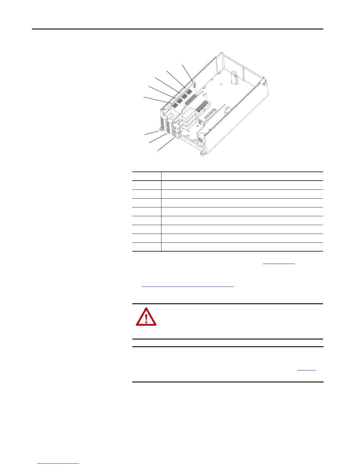
Figure 7 - PowerFlex 700AFE Main Control Board I/O Slots and Jumper Locations
Table 24 - PowerFlex 700AFE Main Control Board I/O and Jumper Locations
See the PowerFlex 700AFE User Manual, publication 20Y-UM001 for I/O
connector wiring and analog configuration jumpers.
See Hardware Enable Circuits
on page 55 for information on how to use
Hardware Enable.
No. Description
1 Analog I/O signals
2 24V DC Digital Inputs
3 Relay Digital Outputs
J1 Analog In 1 voltage/current select
J2 Analog In 2 voltage/current select
J3 Analog Out 1 voltage/current select
J4 Analog Out 2 voltage/current select
J5 Hardware Enable
ATTENTION: Digital Inputs 1, 3, 4, and 5, and Digital Outputs 1 and 2 are
factory-wired and programmed to operate from the controls on the front of
the enclosure door. Do not change the wiring and programming for those
digital inputs and outputs, or the system will malfunction.
IMPORTANT If the existing PowerFlex 700AFE system uses any of the available analog I/O,
you need to supply and configure an appropriate PowerFlex 750 I/O option
module for the replacement PowerFlex 755TM bus supply. See Chapter 2
for
more details.

 Loading...


