Rockwell Automation Publication 750-RM003A-EN-P - April 2018 63
Selection Considerations Chapter 1
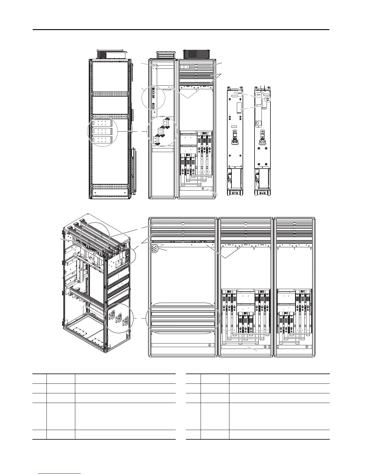
Figure 17 - PowerFlex 755TM Frames 8…12 Bus Supplies
Frame 8 bus supply shown (IP21).
Frame 10 bus supply shown. Layout is typical for Frames 10 through 12.
Item Name Description Item Name Description
1 AC Link Connects AC circuit breaker to LCL fuse assembly 5 Power Bus R/L1, S/L2, T/L3 AC line input power connections
2 AC Bus AC power supply 6 Control Bus 120/240V and 24V AC control power supply connections
3 DC Bus DC+, DC- 7 PE Grounding
Bar
Terminating point to chassis ground for incoming AC line
and motor shield.
PE ground bar clamps, kit number SK-RM-GRNDCLMP-nn,
are available.
4 Test points DC+, DC- and R/L1, S/L2, T/L3 voltage test point sockets 8 Nameplate Power module and LCL filter module nameplate locations

 Loading...


