76 Rockwell Automation Publication 750-RM003A-EN-P - April 2018
Chapter 2 Bus Supply Hardware and Parameter Conversion
Figure 20 and Figure 21 show typical power and control power connections for
a frame 8 PowerFlex 755TM bus supply with the optional control transformer
(-C1 option code). The user-supplied 24V DC auxiliary control power is
shown connected, but the bus supply functions without this power supply.
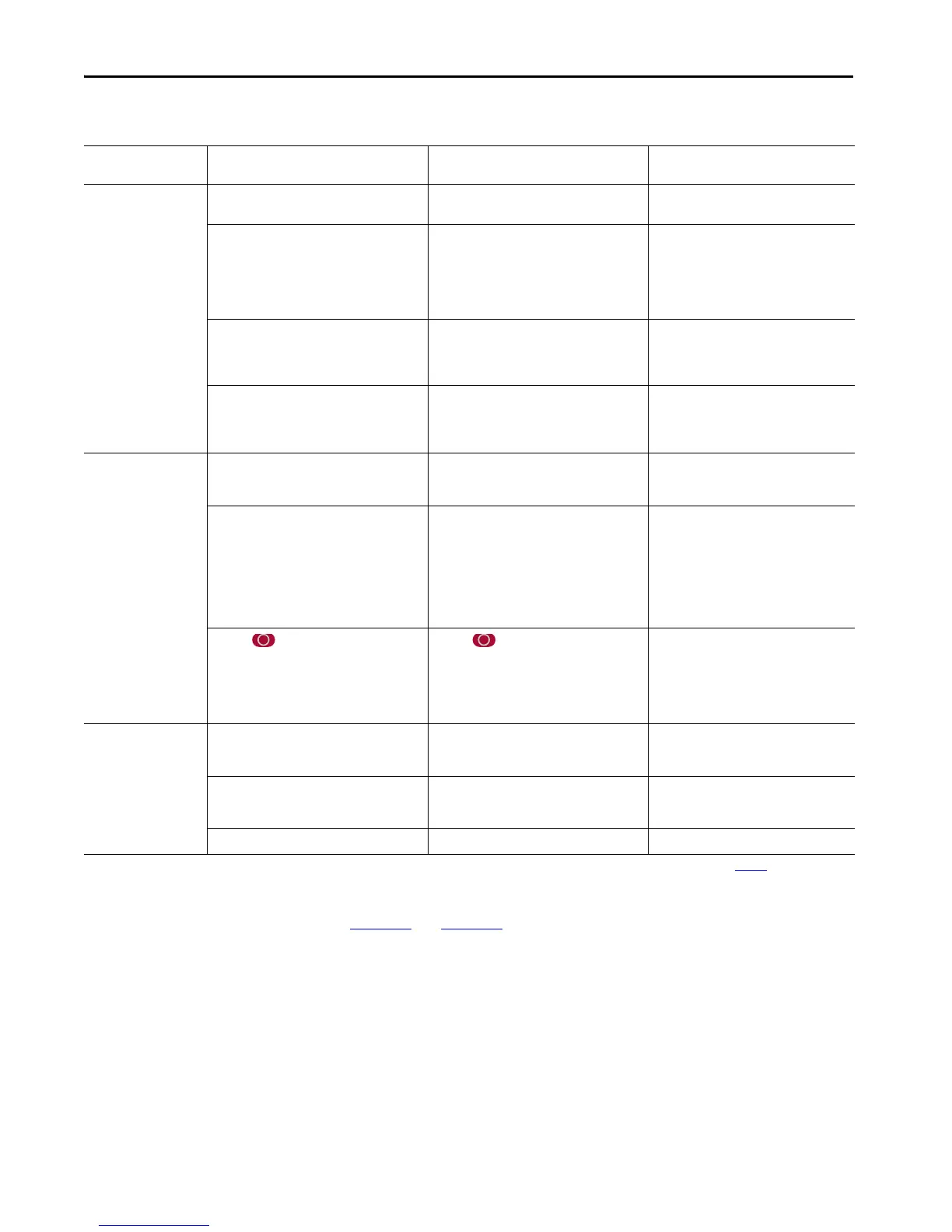
Table 38 - Operation Comparison
Operating Condition PowerFlex 700AFE Bus Supply, IP21 Rittal PowerFlex 700AFE Bus Supply, IP20 2500
MCC
PowerFlex 755TM Bus Supply
3 PH, AC power
application
• Manually energize the main incoming
disconnect circuit breaker (Q0).
• Manually energize the main incoming
disconnect circuit breaker (Q0).
• Manually energize the input disconnect
switch (FD1).
• Initiation of precharge sequence depends on
input from door operator or remote devices
are switched to on/start.
• Precharge contactor (K6) is energized to
supply a separate reduced DC power source to
charge the DC bus.
• Initiation of the precharge sequence depends
on input from door operator or that the
remote devices are switched to on/start.
• Precharge contactor (K6) is energized to
supply a separate reduced DC power source to
charge the DC bus.
• Precharge is initiated immediately.
• Precharge contactor (M1) is energized to
supply reduced AC to LCL filter and
converter. Diodes within the IGBT devices
are used to charge the DC bus.
• When precharge is completed, the MCCB (Q1)
is energized supplying full 3 PH, AC power to
the converter.
• When precharge is completed, the AC
contactor (K1) is energized supplying full
3 PH, AC power to the converter.
• When precharge is completed, the motor-
operated MCB circuit breaker (CB1) is
automatically energized supplying full
3 PH, AC power to the converter.
• When MCCB (Q1) closes and provided there
are no start inhibits, the relay logic
automatically energizes a Digital input
configured to start IGBT modulation.
• When the AC contactor (K1) is energized and
there are no start inhibits, the relay logic
automatically energizes a Digital input that is
configured to start IGBT modulation.
• When the MCB (CB1) is energized and
there are no start inhibits, the user-
configured IGBT modulation stop/start/
run control starts IGBT modulation.
AFE is switched off/
stopped
• The door operator or remote devices are
switched to off.
• The door operator or remote devices are
switched to off.
• User-configured IGBT modulation stop/
start/run control requests stop IGBT
modulation.
• IGBT modulation stops immediately.
• The MCCB (Q1) is de-energized.
• DC bus output voltage decays toward zero.
• Initiation of precharge sequence and restart
of IGBT modulation requires input from the
door operator or remote devices.
• IGBT modulation stops immediately.
• The AC contactor (K1) is de-energized.
• DC bus output voltage decays toward zero.
• Initiation of precharge sequence and restart
of IGBT modulation requires input from the
door operator or remote devices.
• IGBT modulation stops immediately.
• The MCB (CB1) stays energized.
• DC bus output drops to rectification
voltage provided by the IGBT device
diodes.
• Provided there are no start inhibits, IGBT
modulation is restarted by the user-
configured stop/start/run control.
• If the button on the HIM is pressed,
IGBT modulation is stopped, but the MCCB
(Q1) stays energized.
• DC bus output drops to rectification voltage
provided by the IGBT device diodes.
• If the button on the HIM is pressed,
IGBT modulation is stopped but the AC
contactor (K1) stays energized.
• DC bus output will drop to rectification
voltage provided by the IGBT device diodes.
•If Line Side stop
(1)
is true, IGBT
modulation is stopped but the AC circuit
breaker MCB (CB1) stays energized.
• DC bus output drops to rectification
voltage that is provided by the IGBT device
diodes.
AFE is operating with
IGBT modulation,
followed by opening the
input disconnect or loss of
3 PH AC power
• Loss of AC power or manually de-energize the
main incoming disconnect circuit breaker
(Q0).
• Loss of AC power or manually de-energize the
main incoming disconnect circuit breaker
(Q0).
• Loss of AC power or manually de-energize
the input disconnect switch (FD1).
• Loss of AC power and control power causes a
fault and start/run inhibit. IGBT modulation l
stops immediately.
• Loss of AC power and control power causes a
fault and start/run inhibit. IGBT modulation
stops immediately.
• Loss of AC power and control power
causes a fault and start/run inhibit. IGBT
modulation stops immediately.
• The MCCB (Q1) de-energizes. • The AC contactor (K1) de-energizes. • The MCB (CB1) de-energizes.
(1) Line Side stop functionality can only be initiated by digital input 0:112 [DI L Stop] or by communication to Logix controller Add-On-Profile (AOP) Logic Command tags (Table 40). The HIM red button
does not stop IGBT modulation.

 Loading...


