EasyManuals Logo

Allen-Bradley PowerFlex 753 User Manual

Allen-Bradley PowerFlex 753
86 pages
To Next Page IconTo Next Page
To Previous Page IconTo Previous Page
Page #40 background imageLoading...
Page #40 background image
40 Rockwell Automation Publication 750-QS001A-EN-P - March 2015
Reference Section
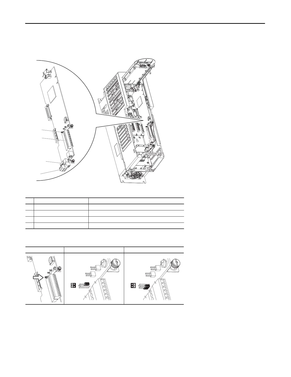
Connections on PowerFlex 753 Main Control Board
Terminal block TB1 and the input mode jumpers are mounted directly on the main control board.
Table 10 - 753 Main Control Board Details
No. Name Description
1 Jumper J4 Input Mode Analog input mode jumper. Selects voltage mode or current mode.
2 TB1 I/O terminal block.
3 TB3 Digital input terminal block.
4 TB2 Relay terminal block.
Table 11 - J4 Input Mode Jumper
Jumper Position Voltage Mode Current Mode
1
2
SK-R1-MCB1-PF753
3
4
J4
3 1
4 2
J4
3 1
4 2

Questions and Answers:

Question and Answer IconNeed help?

Do you have a question about the Allen-Bradley PowerFlex 753 and is the answer not in the manual?

Allen-Bradley PowerFlex 753 Specifications

General IconGeneral
Output Voltage0 to input voltage
Humidity5% to 95% non-condensing
AltitudeUp to 1000 m (3300 ft) without derating
Voltage200-240V AC, 380-480V AC, 500-600V AC
Horsepower1 to 250 HP
EnclosureNEMA/UL Type 1, 12, IP20, IP30, IP54
CommunicationsEtherNet/IP, DeviceNet, ControlNet
Control MethodSensorless Vector Control, V/Hz Control
Input Voltage200-240V AC, 380-480V AC, 500-600V AC
Protection FeaturesOvervoltage, Undervoltage, Overcurrent, Overtemperature
Operating Temperature-10°C to 50°C (14°F to 122°F)
Storage Temperature-40°C to 70°C (-40°F to 158°F)

Related product manuals