Rockwell Automation Publication 750-QS001A-EN-P - March 2015 45
Reference Section
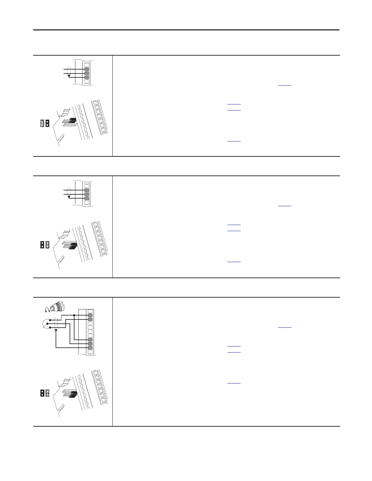
Table 20 - 0…20 mA Analog Input - Unipolar Speed Reference
11-Series I/O Module TB1
Set Direction Mode
Port 0: P308 [Direction Mode] = 0 “Unipolar”
Set Selection
Port 0: P545 [Spd Ref A Sel] = Port 4 (or port where
your 11-Series I/O Module is installed), See page 10: P50 [Anlg In0 Value]
Adjust Scaling
Port 4 (or port where your 11-Series I/O Module is installed), See page
10: P51 [Anlg In0 Hi] = 20 mA
Port 4 (or port where your 11-Series I/O Module is installed), See page
10: P52 [Anlg In0 Lo] = 0 mA or 4 mA
Port 0: P547 [Spd Ref A AnlgHi] = 60 Hz
Port 0: P548 [Spd Ref A AnlgLo] = 0 Hz
View Results
Port 4 (or port where your 11-Series I/O Module is installed), See page
10: P50 [Anlg In0 Value]
Port 0: P592 [Selected Spd Ref]
Jumper set to current mode.
Ai0–
Ai0+
Sh
+
Table 21 - 0…+10V Analog Input - Unipolar Speed Reference
11-Series I/O Module TB1
Set Direction Mode
Port 0: P308 [Direction Mode] =
0 “Unipolar”
Set Selection
Port 0: P545 [Spd Ref A Sel] = Port 4 (or port where
your 11-Series I/O Module is installed), See page 10: P50 [Anlg In0 Value]
Adjust Scaling
Port 4 (or port where your 11-Series I/O Module is installed), See page 10: P51 [Anlg In1 Hi] = 10 Volt
Port 4 (or port where your 11-Series I/O Module is installed), See page
10: P52 [Anlg In1 Lo] = 0 Volt
Port 0: P547 [Spd Ref A AnlgHi] = 60 Hz
Port 0: P548 [Spd Ref A AnlgLo] = 0 Hz
View Results
Port 4 (or port where your 11-Series I/O Module is installed), See page
10: P50 [Anlg In0 Value]
Port 0: P592 [Selected Spd Ref]
Jumper set to voltage mode.
Ai0–
Ai0+
Sh
+
Table 22 - 10k Ohm Potentiometer - Unipolar Speed Reference
11-Series I/O Module TB1
Set Direction Mode
Port 0: P308 [Direction Mode] = 0 “Unipolar”
Set Selection
Port 0: P545 [Spd Ref A Sel] = Port 4 (or port where
your 11-Series I/O Module is installed), See page 10: P50 [Anlg In0 Value]
Adjust Scaling
Port 4 (or port where your 11-Series I/O Module is installed), See page
10: P51 [Anlg In0 Hi] = 10 Volt
Port 4 (or port where your 11-Series I/O Module is installed), See page
10: P52 [Anlg In0 Lo] = 0 Volt
Port 0: P547 [Spd Ref A AnlgHi] = 60 Hz
Port 0: P548 [Spd Ref A AnlgLo] = 0 Hz
View Results
Port 4 (or port where your 11-Series I/O Module is installed), See page
10: P50 [Anlg In0 Value]
Port 0: P592 [Selected Spd Ref]
Jumper set to voltage mode.
10VC
+10V
Ai0–
Ai0+
Sh

 Loading...


