Rockwell Automation Publication 750-QS001A-EN-P - March 2015 57
Reference Section
Communication over EtherNet/IP on 20-750-ENETR Module
You will need the information gathered in Step 2: Validate the Drive Installation, Where are Signal Sources Connected? on
page 10 to complete the EtherNet/IP setup.
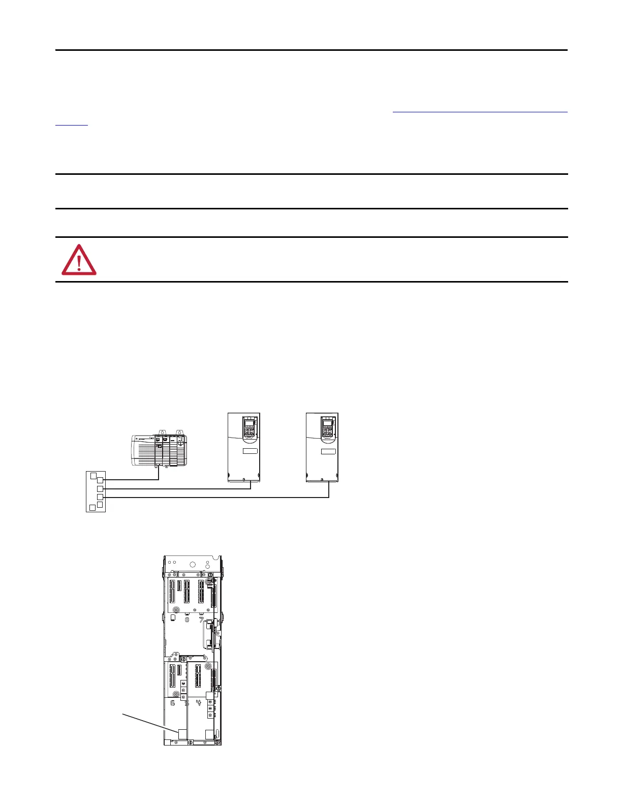
Connecting the Ethernet Cable to the Drive
1. Remove power from the drive.
2. Remove the drive cover and lift up the drive HIM bezel to its open position to access the drive control pod.
3. Use static control precautions.
4. Connect one end of an Ethernet cable to the network. See the following figure for an example of wiring to an
E
t
herNet/IP network.
5. Route the other end of the Ethernet cable through the bottom of the PowerFlex 750-Series drive, and insert the cable
p
l
ug into the EtherNet/IP adapter mating socket.
This section addresses the setup on the PowerFlex 20-750-ENETR Dual-port EtherNet/IP Option module that is installed in Port 6 of
the drive.
ATTENTION: Risk of injury or death exists. The drive may contain high voltages that can cause injury or death. Remove power from
the drive. Verify power has been discharged before connecting the embedded EtherNet/IP adapter to the network.
Ethernet
Switch
Controller
(ControlLogix shown with
1756-ENBT Bridge)
PowerFlex 750-Series Drives
(each with EtherNet/IP adapter)
0
5
4
9
3
8
2
7
1
6
0
5
4
9
3
8
2
7
1
6
0
5
4
9
3
8
2
7
1
6

 Loading...


