EasyManuals Logo
Home>Allen-Bradley>DC Drives>PowerFlex

Allen-Bradley PowerFlex Installation Instructions

Allen-Bradley PowerFlex
16 pages
To Next Page IconTo Next Page
To Previous Page IconTo Previous Page
Page #10 background imageLoading...
Page #10 background image
10 PowerFlex® DC Drive - Frame A Switching Power Supply Circuit Board
2. Remove the plug-in control power terminal block from the Pulse
Transformer circuit board (refer to Figure 1 on page 9
for location).
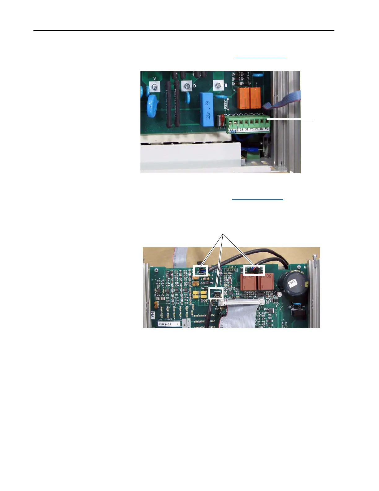
3. Remove the cables from connectors X3, X4 and XP at the top of the
Pulse Transformer board (refer to Figure 1 on page 9
for location).
Note: Connector X4 contains a jumper for drives without a fan - leave in
place.
Remove
plug-in
terminal
block
Remove cables from X3, X4 and XSW

Other manuals for Allen-Bradley PowerFlex

Questions and Answers:

Question and Answer IconNeed help?

Do you have a question about the Allen-Bradley PowerFlex and is the answer not in the manual?

Allen-Bradley PowerFlex Specifications

General IconGeneral
BrandAllen-Bradley
ModelPowerFlex
CategoryDC Drives
LanguageEnglish

Related product manuals