EasyManuals Logo
Home>Allen-Bradley>DC Drives>PowerFlex

Allen-Bradley PowerFlex Installation Instructions

Allen-Bradley PowerFlex
16 pages
To Next Page IconTo Next Page
To Previous Page IconTo Previous Page
Page #11 background imageLoading...
Page #11 background image
PowerFlex® DC Drive - Frame A Switching Power Supply Circuit Board 11
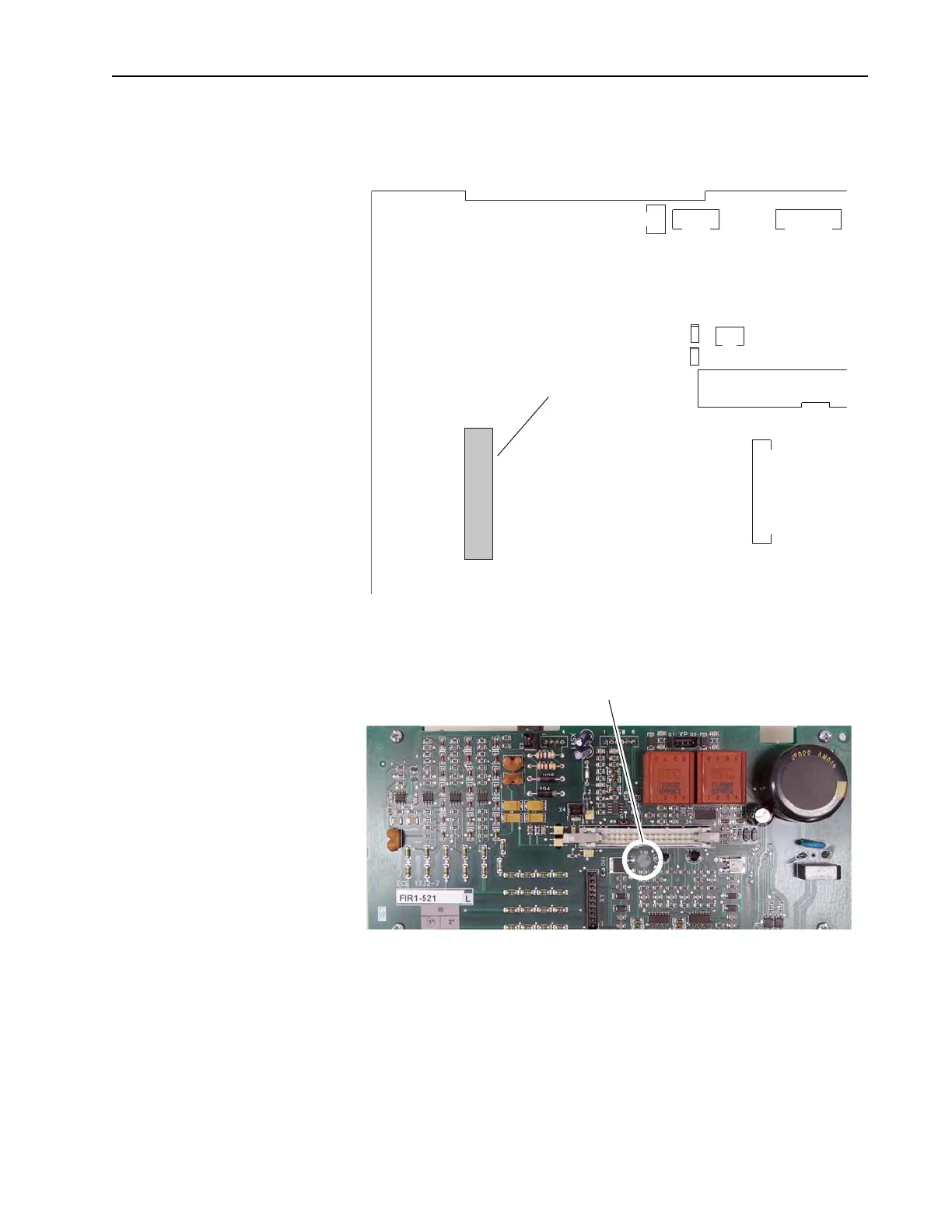
4. For Pulse Transformer boards with an armature voltage feedback
terminal block, FIR1-XX, rev “Q” and higher, remove the connector
from XCD_IO on the upper left corner of the board.
5. Remove the plastic screw near the top of the Pulse Transformer board
and retain for reuse.
XSW1
XSW
X3
XR
X4
XY
XCD_IO
Remove connector from XCD_IO
Remove plastic screw

Other manuals for Allen-Bradley PowerFlex

Questions and Answers:

Question and Answer IconNeed help?

Do you have a question about the Allen-Bradley PowerFlex and is the answer not in the manual?

Allen-Bradley PowerFlex Specifications

General IconGeneral
BrandAllen-Bradley
ModelPowerFlex
CategoryDC Drives
LanguageEnglish

Related product manuals