Rockwell Automation Publication PFLEX-AP005B-EN-P - May 2019 43
Drive Selection Considerations Chapter 1
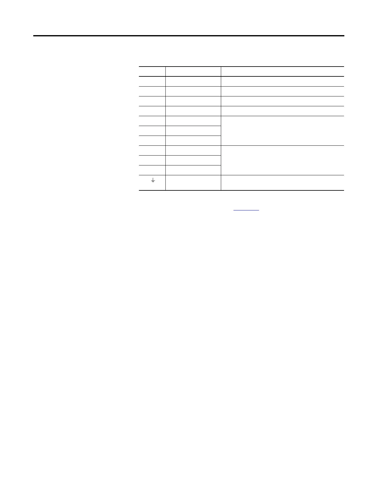
Table 21 - PowerFlex 750-Series Frames 2…7 Power Terminal Block Designations
Terminal Description Notes
+DC DC Bus (+) DC Input Power or Dynamic Brake Chopper
-DC DC Bus (–) DC Input Power or Dynamic Brake Chopper
BR1 DC Brake (+) Dynamic Brake Resistor Connection (+)
BR2 DC Brake (–) Dynamic Brake Resistor Connection (–)
U U (T1) Motor Connections
(1)
(1) Important: Motors with NEMA MG1 Part 31.40.4.2 inverter grade insulation systems are recommended. If you
intend to connect a motor that is not rated inverter grade, refer to Wiring and Grounding Guidelines for Pulse
Width Modulated (PWM) AC Drives, publication DRIVES-IN001
, for recommendations.
VV (T2)
WW (T3)
R R (L1) AC Line Input Power
SS (L2)
T T (L3)
PE / PE Ground Terminating point to chassis ground for incoming AC line
and motor shield.

 Loading...


