30 Rockwell Automation Publication PFLEX-AP005B-EN-P - May 2019
Chapter 1 Drive Selection Considerations
Power Terminal
Comparison
PowerFlex 700 Drives
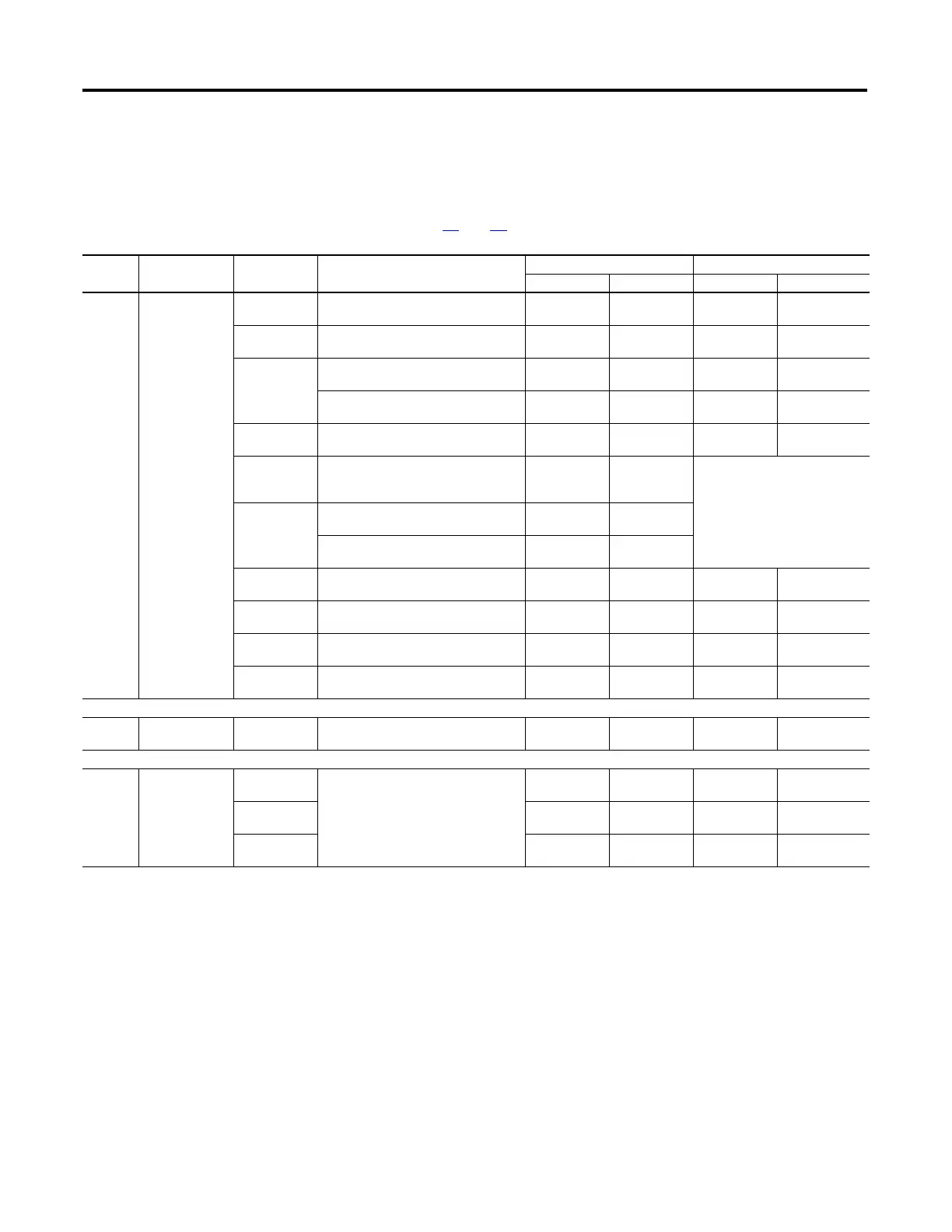
Table 12 - PowerFlex 700 Drives Terminal Block Specifications
Refer to pages 32 and 33 for typical locations.
Location
No. Name Frame Description
Wire Size Range
(1)
Torque
Maximum Minimum Maximum Recommended
1 Power Terminal
Block
0 and 1 Input power and motor connections 4.0 mm
2
(12 AWG)
0.5 mm
2
(22 AWG)
1.7 N•m
(15 lb.•in.)
0.8 N•m
(7 lb.•in.)
2 Input power and motor connections 10.0 mm
2
(8 AWG)
0.8 mm
2
(18 AWG)
1.7 N•m
(15 lb.•in.)
1.4 N•m
(12 lb.•in.)
3 Input power and motor connections 25.0 mm
2
(3 AWG)
2.5 mm
2
(14 AWG)
3.6 N•m
(32 lb.•in.)
1.8 N•m
(16 lb.•in.)
BR1, 2 terminals 10.0 mm
2
(8 AWG)
0.8 mm
2
(18 AWG)
1.7 N•m
(15 lb.•in.)
1.4 N•m
(12 lb.•in.)
4 Input power and motor connections 35.0 mm
2
(1 AWG)
10.0 mm
2
(8 AWG)
4.0 N•m
(35 lb.•in.)
4.0 N•m
(35 lb.•in.)
5
75Hp, 480V
100Hp, 600V
Input power, DC+, DC–, BR1, 2, PE,
motor connections
50.0 mm
2
(1/0 AWG)
4.0 mm
2
(12 AWG)
See Note
(2)
5
100Hp
Input power, DC+, DC– and motor 70.0 mm
2
(2/0 AWG)
10.0 mm
2
(8 AWG)
BR1, 2, PE terminals 50.0 mm
2
(1/0 AWG)
4.0 mm
2
(12 AWG)
6 Input power, DC+, DC–, BR1, 2, PE,
motor connections
150.0 mm
2
(300 MCM)
(2)
2.5 mm
2
(14 AWG)
6.0 N•m
(52 lb.•in.)
6.0 N•m
(52 lb.•in.)
7 Input power, DC+, DC–, PE, motor
connections
150.0 mm
2
(300 MCM)
(2)
2.5 mm
2
(14 AWG)
2.7 N•m
(24 lb.•in.)
2.7 N•m
(24 lb.•in.)
8 and 9 Input power, DC+, DC–, PE, motor
connections
300.0 mm
2
(600 MCM)
(2)
2.5 mm
2
(14 AWG)
10.0 N•m
(87 lb.•in.)
10.0 N•m
(87 lb.•in.)
10 Input power, DC+, DC–, PE, motor
connections
300.0 mm
2
(600 MCM)
(2)
2.5 mm
2
(14 AWG)
10.0 N•m
(87 lb.•in.)
10.0 N•m
(87 lb.•in.)
2 SHLD Terminal 0…6 Terminating point for wiring shields — — 1.6 N•m
(14 lb.•in.)
1.6 N•m
(14 lb.•in.)
3 AUX Terminal
Block
0…4 Auxiliary control voltage
PS+, PS–
(3)
(4)
1.5 mm
2
(16 AWG)
0.2 mm
2
(24 AWG)
——
5…6 4.0 mm
2
(12 AWG)
0.5 mm
2
(22 AWG)
0.6 N•m
(5.3 lb.•in.)
0.6 N•m
(5.3 lb.•in.)
7…10 4.0 mm
2
(12 AWG)
0.049 mm
2
(30 AWG)
0.6 N•m
(5.3 lb.•in.)
0.6 N•m
(5.3 lb.•in.)
(1) Maximum/minimum sizes that the terminal block will accept—these are not recommendations.
(2) Refer to the terminal block label inside the drive.
(3) External control power: UL Installation-300V DC, 10%, Non UL Installation-270…600V DC, 10% (0…3 Frame-40W, 165 mA, 5 Frame-80W, 90 mA).
(4) An auxiliary control power supply, such as the 20-24V-AUX, can be used with 400/480 and 600/690 volt drives with Vector Control. However, consult the factory before
using an auxiliary power supply in these instances. Important: The auxiliary control power supply must not be used with any Standard Control drive or any 200/240V
PowerFlex 700 drive, Standard or Vector Control.

 Loading...


