SLC 500 BASIC and BASIC-T Modules 25
Publication 1746-IN009B-EN-P - August 2005
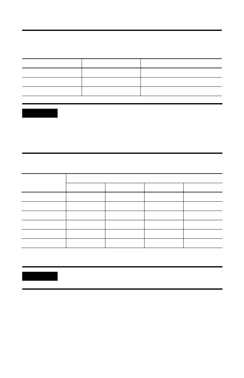
Operating Voltage and Current Requirement
Component Operating Voltage Current Requirement
Hand-Held Terminal 24V dc 0.105 A
Data Table Access Module 24V dc 0.104 A
Interface Converter 24V dc 0.060 A
IMPORTANT
The module receives its power from the SLC backplane. The
power consumption of the module must be taken into
consideration when planning your SLC 500 system. Refer to the
documentation supplied with your SLC 500 fixed or modular
controller for additional information on power supplies and
current requirements.
Communication Maximum Distance Allowed in Meters (Feet)
Rate (bps) RS-232 RS-423 RS-422 RS-485
300 15 (50) 1230 (4000) 1230 (4000) 1230 (4000)
600 15 (50) 920 (3000) 1230 (4000) 1230 (4000)
1200 15 (50) 770 (2500) 1230 (4000) 1230 (4000)
4800 15 (50) 245 (800) 1230 (4000) 1230 (4000)
9600 15 (50) 120 (400) 1230 (4000) 1230 (4000)
19200 15 (50) 60 (200) 1230 (4000) 1230 (4000)
IMPORTANT
Use the RS-423 jumper settings when communicating in RS-232
mode.