Do you have a question about the Allen-Bradley PowerMonitor 500 and is the answer not in the manual?
Details the content, scope, and purpose of the user manual, including topics like mounting, wiring, and operation.
Explains the meaning of each part of the PowerMonitor 500 catalog number for model identification.
Lists related Rockwell Automation documents and websites for further information on products and compliance.
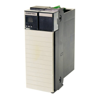
Describes the capabilities, models, and specifications of the PowerMonitor 500 unit, including voltage ranges and outputs.
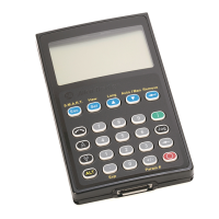
Details the buttons, indicators, and their functions on the front panel of the unit for operation and navigation.
Explains the icons, indicators, and display elements used on the PowerMonitor 500 for status and measurement readings.
Guides on navigating and selecting data to be shown on the front panel display for monitoring various parameters.
Provides dimensions and panel cut-out details for installing the PowerMonitor 500 unit into a panel.
Explains how to connect the unit for various system types (3-phase, single-phase) using wiring diagrams.
Details how to connect the unit to a power supply, including safety precautions and overcurrent protection.
Shows wiring diagrams for optional modules like pulse, analog, and communication ports for proper connection.
Outlines the menu-based configuration process using the unit's front panel display for setting parameters.
Presents a visual guide to the unit's configuration menus and submenus for systematic setup.
Explains how to use digital filters (FILTER S, FILTER CO) to stabilize fluctuating measurements.
Provides examples for configuring analog outputs for retransmission of power and power factor values.
Demonstrates how to set up alarms based on real power thresholds and link them to relay outputs.
Covers EtherNet/IP support, assembly instances, data access methods, and message setup with CIP Generic.
Details Modbus RTU and TCP/IP support, functions, data types, and register formats for communication.
Indexes all available data tables, their Modbus addresses, CIP instances, and number of elements.
Lists data tables for real-time voltage, current, power, PF, and frequency measurements.
Details data tables for maximum recorded voltage, current, power, PF, and frequency.
Provides data tables for demand (DMD) values of voltage, current, power, PF, and frequency.
Lists electrical input parameters like voltage, current, frequency, accuracy, and overloads.
Describes core functionalities such as password, system selection, filtering, display options, and virtual alarms.
Covers environmental, safety, EMC, insulation, and compliance specifications for the unit.
Describes the CIP Objects, Instances, and their relationships for EtherNet/IP communication and data access.
Explains how to retrieve specific attributes from the Identity Object using message instructions in Logix Designer.
Details the nine Assembly Instances (100d-108d) used for data access via EtherNet/IP scheduled connections.
Provides links and information to access technical support resources, knowledge base, and product updates.
Offers a channel for users to provide suggestions for improving the manual's content and clarity.
| Model | PowerMonitor 500 |
|---|---|
| Communication Ports | RS-485, Ethernet |
| Mounting | Panel Mount |
| Current Inputs | 3 |
| Display | LCD |
| Communication Protocols | Modbus RTU, EtherNet/IP |
| Measurement Parameters | Voltage, Current, Power, Energy, Power Factor, Frequency |
| Enclosure Rating | IP20 |
| Accuracy | ±0.5% of reading |