R
Robert SantosAug 3, 2025
What does flashing red mean on an Allen-Bradley POINT I/O 1734-232ASC?
- JJohn BerryAug 3, 2025
If your Allen-Bradley Control Unit is flashing red, it means a recoverable fault has occurred.

What does flashing red mean on an Allen-Bradley POINT I/O 1734-232ASC?
If your Allen-Bradley Control Unit is flashing red, it means a recoverable fault has occurred.
What does solid red mean on Allen-Bradley POINT I/O 1734-232ASC Control Unit?
If the Allen-Bradley Control Unit shows a solid red light, it indicates an unrecoverable fault. Device replacement may be required.
What to do if the Allen-Bradley Control Unit module status is off?
If the Allen-Bradley Control Unit module status is off, it indicates that no power is being supplied to the device. You should check the power supply and make sure it is properly connected.
Why is my Allen-Bradley POINT I/O 1734-232ASC Control Unit flashing green?
If the Allen-Bradley Control Unit is flashing green, it means the device needs commissioning because the configuration is missing, incomplete, or incorrect.
What does flashing red/green mean on Allen-Bradley POINT I/O 1734-232ASC Control Unit?
If the Allen-Bradley Control Unit is flashing red and green, it indicates that the device is currently running a self-test.
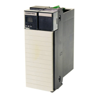
| Brand | Allen-Bradley |
|---|---|
| Model | POINT I/O 1734-232ASC |
| Category | Control Unit |
| Language | English |
Explains how to correctly key and insert an I/O module into the mounting base, with safety warnings.
Describes the process of reinserting the removable terminal block (RTB) into the base unit.
Explains wiring requirements, shielded cable necessity, and proper grounding techniques.
Details steps to read data from serial devices, including configuration and monitoring.
Explains how to send data to serial devices, covering data, length, and transaction ID parameters.
Guides on configuring serial links and I/O connections, including input/output sizes.
Provides steps to add the module to the network using RSNetWorx software.
Guides on adding I/O modules to the network and configuring their node addresses.
Explains how to access and view module parameters through a pop-up screen with various tabs.
Details editing parameters via the "Parameters" tab and downloading changes to the module.
Explains how the module receives characters and transmits them to the DeviceNet master.
Describes data transmission from DeviceNet to ASCII devices via I/O or explicit messages.
Explains how to interpret module and network status indicators for troubleshooting.
Lists module/network status indications and their probable causes for troubleshooting.
Shows RSNetWorx mapping for reading data into ControlLogix, including header byte locations.
Illustrates ladder logic for monitoring transaction IDs and copying received data.
Shows RSNetWorx mapping for transmitting data from ControlLogix via the module's header.
Illustrates ladder logic for counter incrementing and updating transmit transaction IDs.