Rockwell Automation Publication 1420-UM001E-EN-P - March 2016 23
Installation and Wiring Chapter 2
Factory Installed Option Wiring
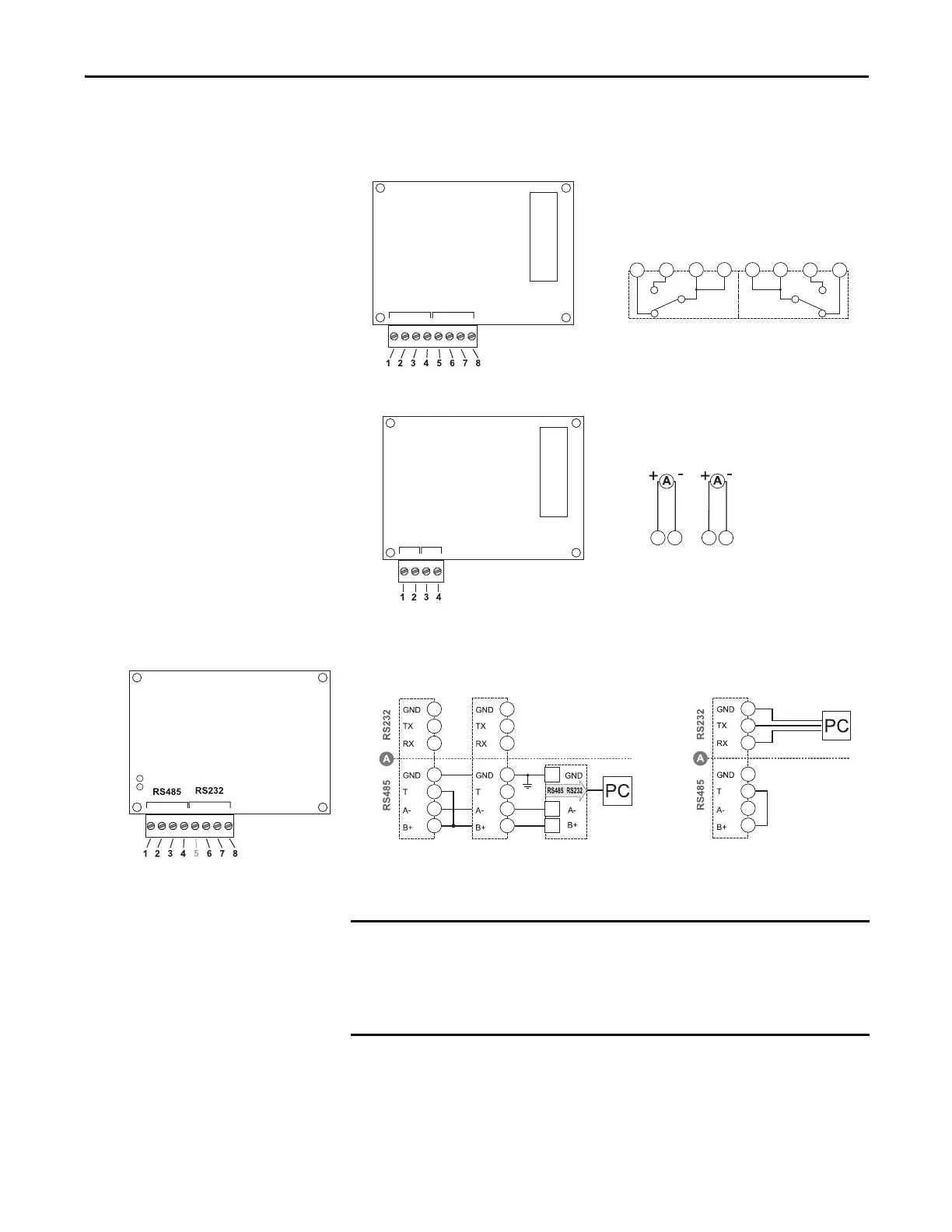
Figure 18 - Pulse (digital) Outputs (P option)
Figure 19 - Analog Outputs (A option)
Figure 20 - Serial RS-485 and RS-232 Communication Wiring (485 option)
Out 1 Out 2
Out 1 Out 2
2143
6587
1432
Out 1 Out 2
Out 1
Out 2
Analog 20 mA DC
RS-485 Port RS-232 Port
6
7
8
1
2
3
4
6
7
8
1
2
3
4
6
7
8
1
2
3
4
Mandatory
Termination
T = Termination
A- = Transmit minus
B+ = Transmit plus
Additional devices that are provided with RS-485 are connected in parallel. The
termination of the serial output is implemented only on the last instrument of
the network, with a jumper between (B+) and (T). The jumper applies an
internal termination resistance between (A-) and (B+). The RS-232 and
RS-485 communication ports cannot be connected and used simultaneously.

 Loading...