Rockwell Automation Publication 1420-UM001E-EN-P - March 2016 19
Installation and Wiring Chapter 2
Wiring Diagrams
The PowerMonitor™ 500 unit can monitor various three-phase, single-phase, and
split-phase circuits. Select the voltage connections, current wiring, and system
metering mode to match the configuration of the circuit being monitored.
Table 4
provides a key for you to select the proper wiring diagrams and system
metering modes.
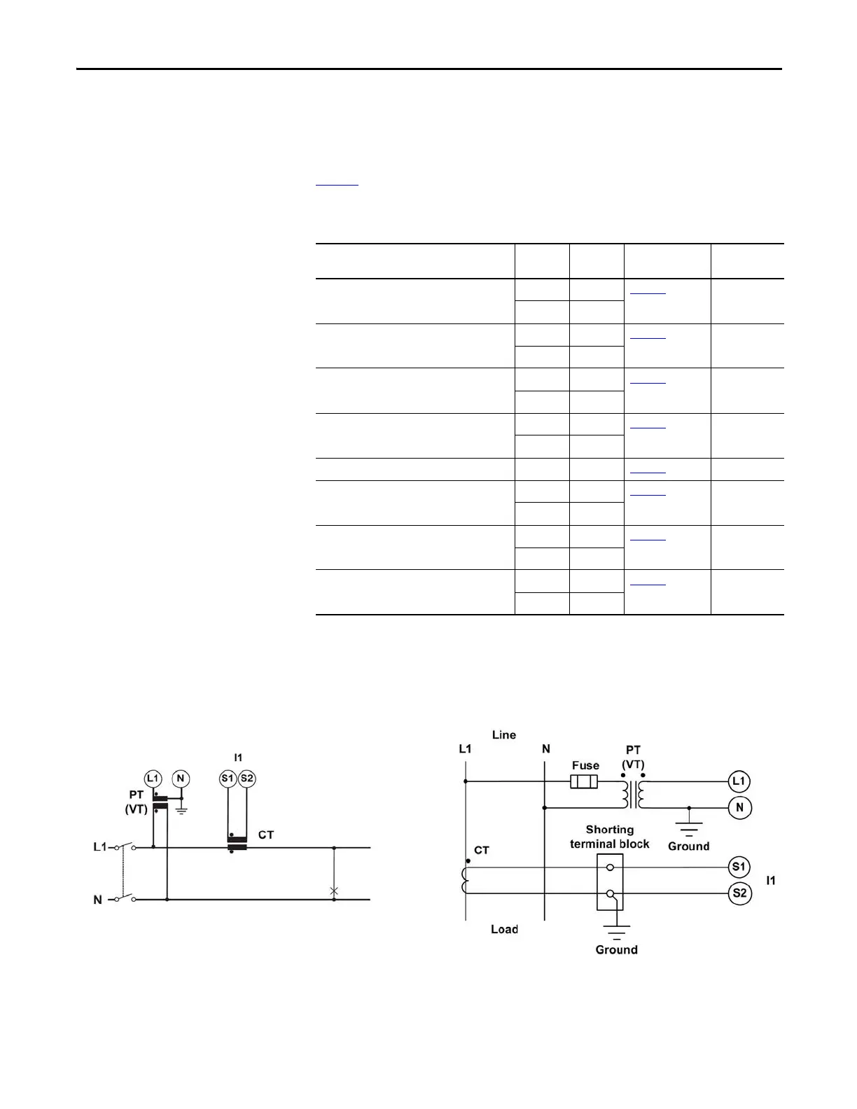
The wiring diagrams in this manual are drawn with U.S. (NEMA) conventions.
For convenience, a connection diagram is shown in IEC style on the left and in its
corresponding NEMA style (used in the U.S.) on the right.
Figure 10 - Wiring Diagram Interpretation
Table 4 - Wiring Diagram Explanation
Circuit type No. of CTs No. of PTs Wiring Diagram System
Configuration
3-phase, 4-wire Wye Unbalanced load 3 - Figure 12
3P.n
33
3-phase, 2-wire Wye Balanced load 1 - Figure 11 3P.2
11
3-phase, 3-wire Delta Unbalanced load 3 - Figure 13
3P
2-
Open Delta Unbalanced load 3 2 Figure 13
3P
22
Open Delta Balanced load 1 2 Figure 14 3P.1
3-phase, Single CT Balanced load 1 - Figure 14
3P.1
13
Split-phase 2 - Figure 15 2P
22
Single phase 1 - Figure 16
1P
11

 Loading...