36 Rockwell Automation Publication 1420-UM001E-EN-P - March 2016
Chapter 3 Unit Configuration
Alarm Configuration
Example
These examples apply to units with catalog numbers 1420-V1P and 1420-V2P.
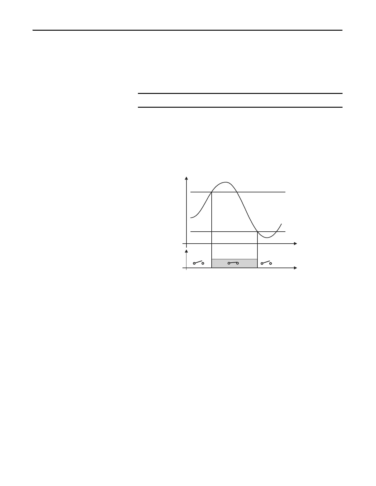
This example describes an alarm when a measured real power value exceeds a
programmed threshold. For example, when 300 kW are exceeded, the alarm
occurs and the load that is controlled by the relay output is disconnected.
An ‘UP’ alarm is selected. The recommended programming is the following:
• ENABLE: YES
• VARIABLE S : W system (W·)
• SET POINT 1: 300 kW
• SET POINT 2: 295 kW
• ON DELAY: set the desired number of seconds, for example 5 seconds
To program a ‘DOWN’ alarm, configure SET POINT 1 to be a lower value than
SET POINT 2.
The PowerMonitor 500 unit is not intended to be applied as a protective device.

 Loading...