12 SLC 500 BASIC and BASIC-T Modules
Publication 1746-IN009B-EN-P - August 2005
Install the 1746-BAS Module and 1746-BAS-T Module
Your BASIC module or BASIC-T module may be installed in any open slot of an SLC
500 1746 I/O chassis except the first slot of the first chassis. The first slot is reserved
for the controller or adapter module. The BASIC module or BASIC-T module can
also be installed in an SLC fixed controller expansion chassis.
1. Turn off power to the chassis where you will insert the module.
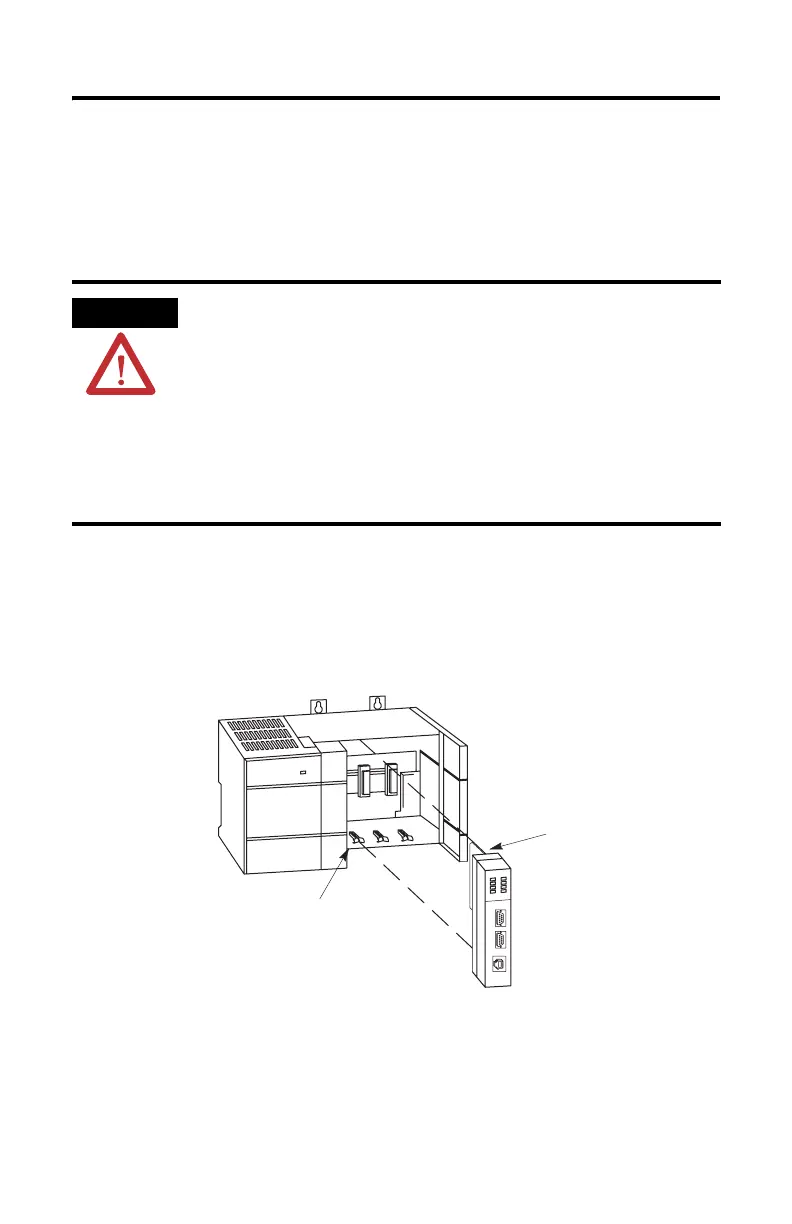
2. Align the circuit board of the module with the card guide of a slot (except
slot 0) in the 1746 chassis.
Figure 7 Module Location in the Chassis
3. Slide the module in until the top and bottom retainer clips are secured.
ATTENTION
Never install, remove, or wire any module while power is applied.
Also, do not expose the modules to surfaces or other areas that
may typically hold an electrostatic discharge.
Electrostatic discharge can damage integrated circuits or
semiconductors if you touch backplane connector pins.
If the equipment is not installed and used as described in the SLC
500 Modular Hardware Style User Manual, publication
1747-UM011, the protection provided by the equipment may be
impaired.
Card Guide
Module Release