ASSEMBLY INSTRUCTIONS
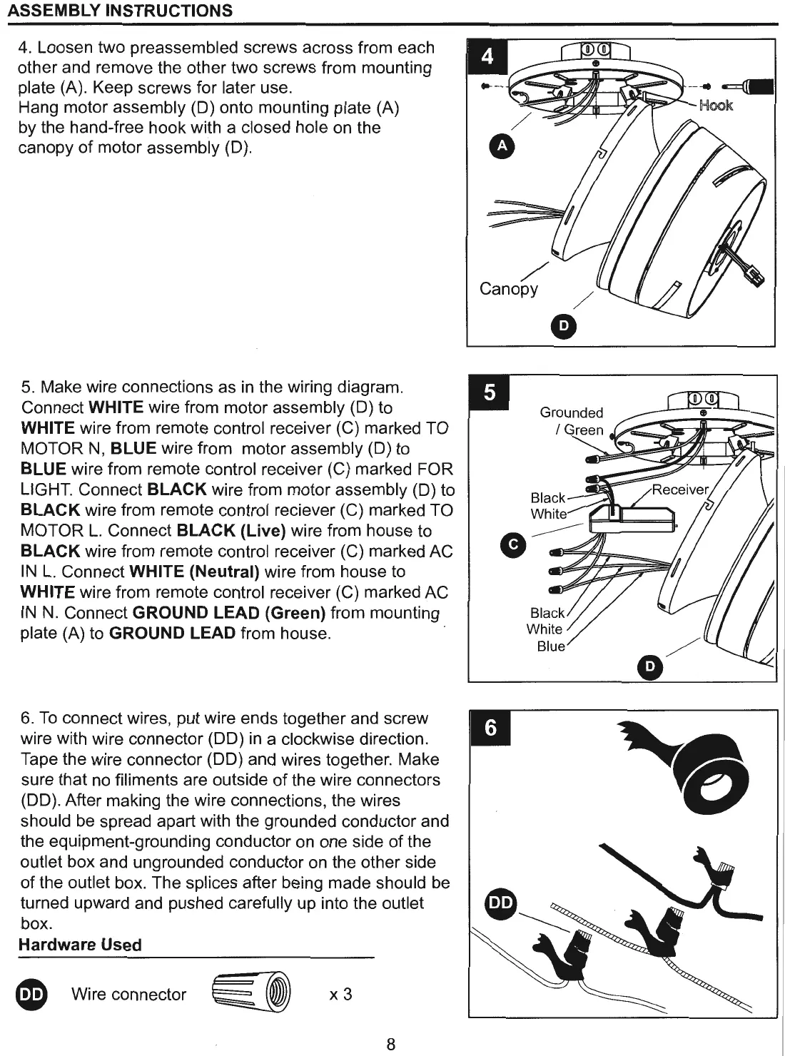
4. Loosen two preassembled screws across from each
other and remove the other two screws from mounting
plate (A). Keep screws for later use.
Hang motor assembly (D) onto mounting plate (A)
by the hand-free hook with a closed hole on the
canopy
of
motor assembly (D).
5.
Make wire connections as in the wiring diagram.
Connect
WHITE wire from motor assembly (D) to
WHITE wire from remote control receiver (C) marked TO
MOTOR
N,
BLUE wire from motor assembly (D) to
BLUE wire from remote control receiver (C) marked FOR
LIGHT. Connect
BLACK wire from motor assembly (D) to
BLACK wire from remote control reciever (C) marked TO
MOTOR
L.
Connect BLACK (Live) wire from house to
BLACK wire from remote control receiver (C) marked AC
IN
L.
Connect WHITE (Neutral) wire from house to
WHITE wire from remote control receiver (C) marked AC
IN
N.
Connect GROUND LEAD (Green) from mounting
plate (A) to
GROUND LEAD from house.
6.
To
connect wires, put wire ends together and screw
wire with wire connector
(DO) in a clockwise direction.
Tape the wire connector
(DO) and wires together. Make
sure that no filiments are outside
of
the wire connectors
(DO). After making the wire connections, the wires
should be spread apart with the grounded conductor and
the equipment-grounding conductor on one side
of
the
outlet box and ungrounded conductor on the other side
of
the outlet box. The splices after being made should be
turned upward and pushed carefully up into the outlet
box
.
Hardware Used
~
Wire connector
~
x 3
8
/
0
/
G
Grounded
 Loading...