M413487 29
Section 5 Service Procedures
To reduce the risk of electric shock, fire, explosion, serious injury or death:
• Disconnect electric power to the tumbler before servicing.
• Close gas shut-off valve to gas tumbler before servicing.
• Close steam valve to steam tumbler before servicing.
• Never start the tumbler with any guards/panels removed.
• Whenever ground wires are removed during servicing, these ground wires must be
reconnected to ensure that the tumbler is properly grounded.
W002
WARNING
© Copyright, Alliance Laundry Systems LLC – DO NOT COPY or TRANSMIT
28. OPL MICRO CONTROL
Refer to Figure 6 or Figure 7.
a. Remove micro control face plate.
b. Remove two micro control mounting plate
screws and rotate mounting plate downward.
c. Disconnect wires/harnesses.
IMPORTANT: Due to sensitivity of micro control,
careful handling is required. As a precautionary
measure, we recommend using a grounded wrist
strap when handling micro control. Wrist strap,
cord and alligator clip are designed to carry away
any electrostatic charge from your body and to
direct charge to an available ground.
Handle micro control circuit board by the sides
only. Do not contact circuit boards with hands or
metal objects. Place micro control in a clean, dry
area away from work area to avoid damage. Do not
attempt field repair of the micro control. Attempted
repair or tampering with the micro control will void
its warranty.
d. Remove four nuts and micro control from
mounting plate.
29. EMERGENCY STOP BUTTON - DC, JC
AND SC MODELS
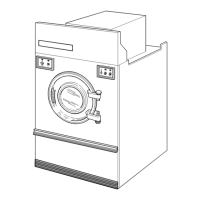
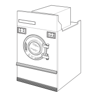
a. Remove four screws holding access panel to
cabinet. Refer to Figure 1.
b. Lift access panel off top edge of front panel and
pull panel forward. Refer to Figure 1.
c. Remove control box cover. Refer to Figure 2.
d. Remove emergency stop button from contact
block. Refer to Figure 5 or Figure 7.
30. IGNITION RESET SWITCH - DC, JC AND
SC MODELS
a. Remove four screws holding access panel to
cabinet. Refer to Figure 1.
b. Lift access panel off top edge of front panel and
pull panel forward. Refer to Figure 1.
c. Remove control box cover. Refer to Figure 2.
d. Disconnect wires from ignition reset switch.
e. Remove ignition reset switch. Refer to Figure 4
or Figure 7.
MICRO CONTROL MM MODELS
Figure 6
T331PE1A
REVERSING/NONREVERSING
SWITCH
MICRO CONTROL
MICRO
MOUNTING
PLATE
FACE PLATE
 Loading...