45-009 REV. 8/20
29
SECTION 6 SERVICE PROCEDURE
6.1 Attachment Removal
1. Position the attachment arms to the width of the unit’s body.
WARNING
Crush hazard.
Serious injury could result if residual hydraulic pressure
causes equipment to drift during service procedures.
Turn off truck's power, and activate hydraulic functions in
both directions to bleed off hydraulic pressure.
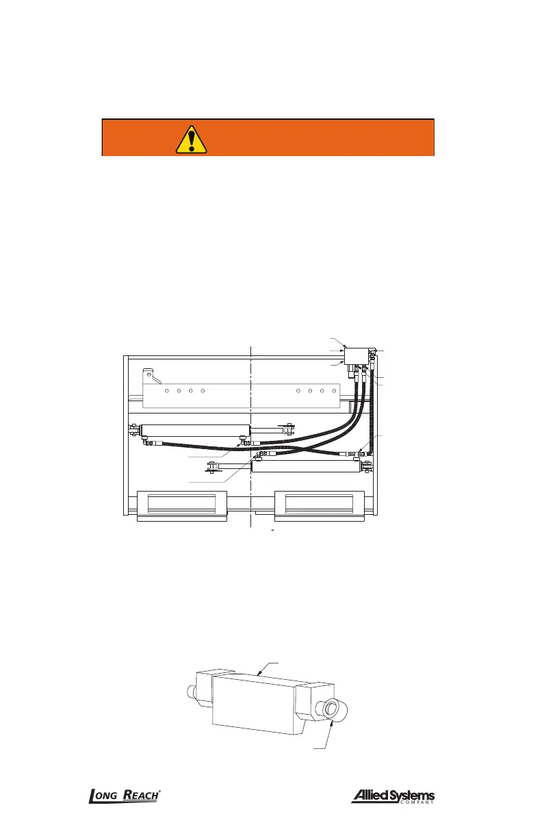
2. Disconnect the hydraulic connection for the attachment positioning at the hydraulic
valve, ports V1 and V2 (Figure 6-1). Cap hoses to prevent contamination, and tag
for reassembly.
Valve Flow/Relief
Truck Connection Port V2
Truck Connection Port V1
Port C3
S
Port C2
From C2
From C1
From C3
Port C1
Figure 6-1, Hydraulic Connection, Right Hand Terimination (Standard)
3. Disconnect the sideshift connections, if applicable. Cap hoses to prevent contami-
nation, and tag for reassembly.
4. Slightly raise the truck carriage to allow the removal of the bottom mounting hooks.
If the attachment is equipped with quick change hooks, simply remove retaining pin
and pull lower hooks down. (See Figure 6-2)
Retaining pin
Quick change hook
Figure 6-2, Quick Change Hook
 Loading...