45-009 REV. 8/20
35
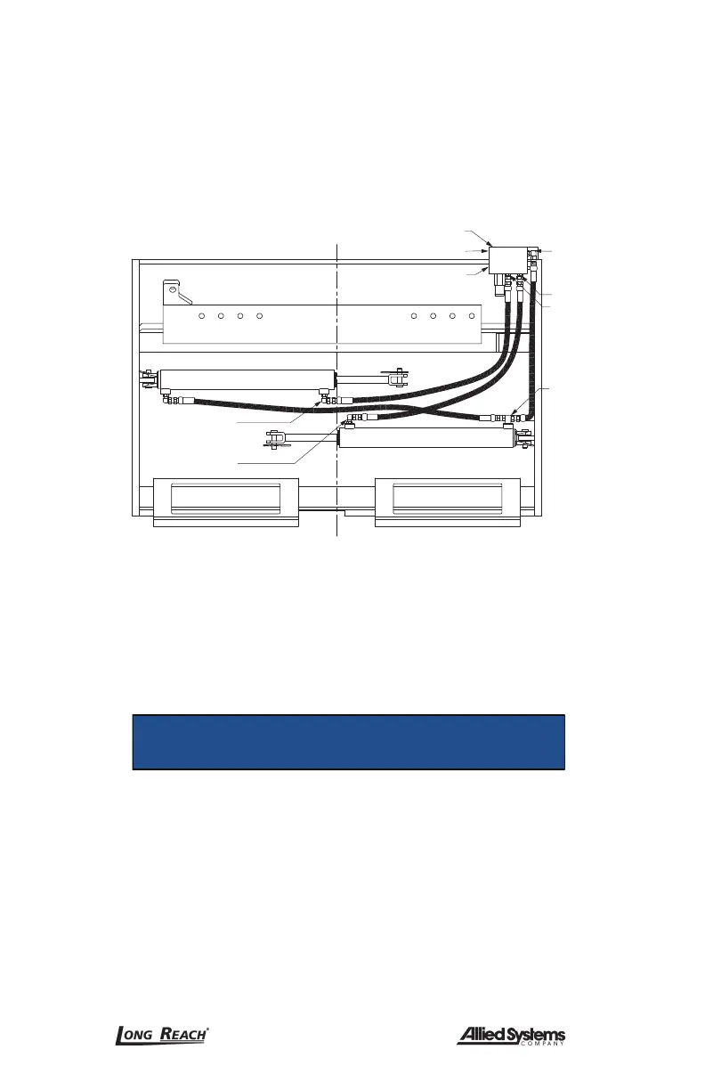
2. Disconnect the hydraulic hoses from the truck at the attachments valve ports V1
(open) and V2 (close). (Figure 6-9). Cap hoses to prevent contamination, and tag
for reassembly.
3. Disconnect the hydraulic hoses at the valve ports C1 and C2. Cap hoses to prevent
contamination, and tag for reassembly.
4. Remove the valve mounting bolts and remove valve.
Valve Flow/Relief
Truck Connection Port V2
Truck Connection Port V1
Port C3
Port C2
From C2
From C1
From C3
Port C1
Figure 6-9, Hydraulic Hoses, Right Hand Termination (Standard)
6.8 Hydraulic Valve Installation
1. Reassemble in the reverse order of Section 6.7.
2. Turn on the truck’s power and activate the hydraulic functions serveral times to
bleed out trapped air.
NOTICE
Equipment damage hazard.
Equipment damage and loss of performance could result
if air is trapped in the hydraulic system.
Activate the hydraulic functions several times after
hydraulic service has been performed, to bleed trapped air
out of the system before returning attachment to service.
 Loading...