45-009 REV. 8/20
33
6.5 Cylinder Assembly
1. Spray the piston, gland cap, and seals with WD40 or other similar product to ease
slipping the seals in place.
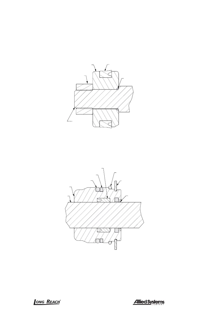
2. Note the direction of the seal on the piston. Improper installation will result in poor
performance. The cupped side or O-ring side of the seal should be facing the gland
cap. (Figure 6-7)
O-Ring
Seal
Piston nut
Piston
Cylinder
rod
Figure 6-7, Piston Seal
3. Install the seals and wipers in the gland cap. Note the direction of the seals. The
cupped side or O-ring side of the seal should be facing the piston (Figure 6-8).
Refer to your parts manual for information specific to your model.
Wiper ring
Lock ring
Retaining
ring
O-Ring
Backup ring
Seal
Gland
Cylinder
rod
Figure 6-8, Gland Cap Seal
4. Install the gland cap on the cylinder rod being extremely careful not to cut the rod
seal on the threads of the rod or rod shoulder. If available, use a sleeve or plastic
electrical tape to cover the rod threads.
5. Install the piston on the rod and tighten the locknut to the proper torque as described
below.
 Loading...