45-009 REV. 8/20
31
4. Push gland inward 1 inch and pry out lock ring.
5. Remove the rod assembly from the cylinder tube.
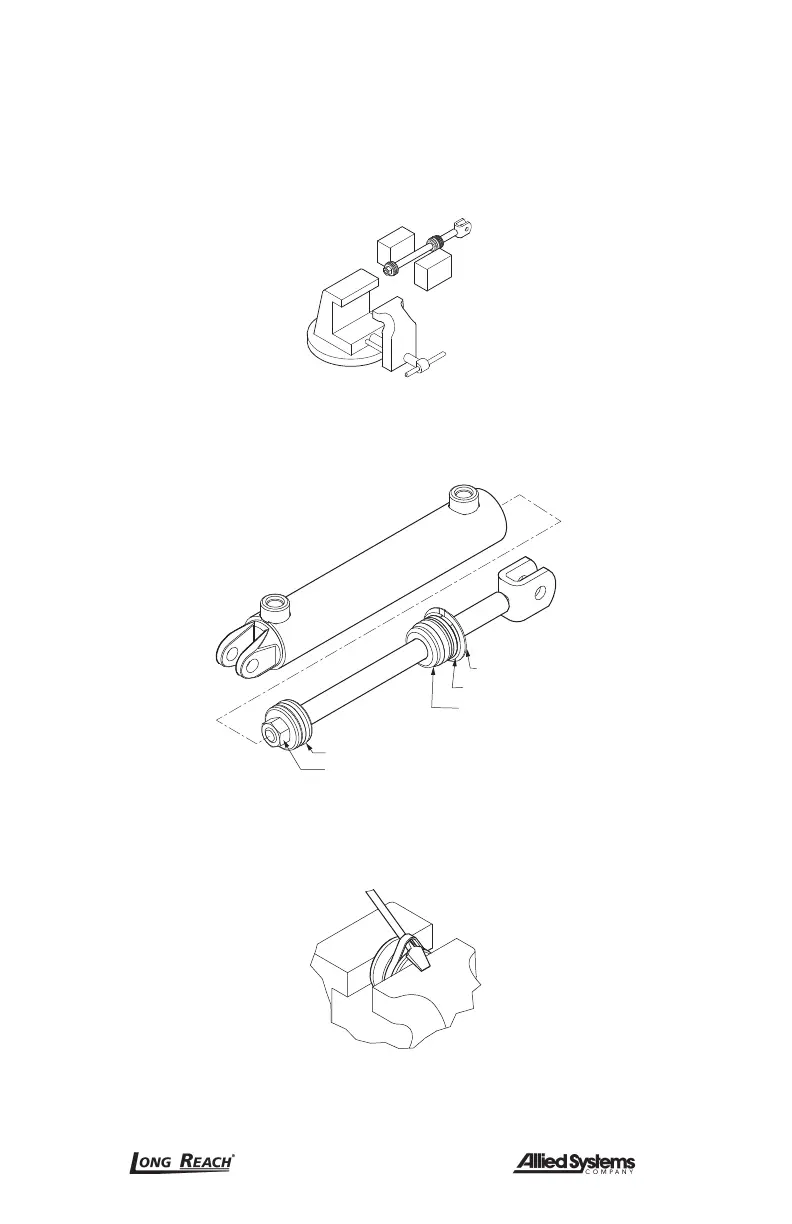
6. Clamp the rod assembly in a soft jawed vise on the wrench flats, not on the rod
surface. If the rod does not have wrench flats use two pieces of wood on both
sides of the rod to prevent scarring. (Figure 6-4)
Figure 6-4, Cylinder Shaft
7. Remove the piston retaining nut and remove the piston. (Figure 6-5)
Piston Nut
Piston
Gland/Cylinder
Head
Lock Nut/Ring
Retaining Ring
Figure 6-5, Rod Assembly
8. Carefully pry up on the piston seals using a blunt tip screw driver being careful not
to scratch the seal grooves. Cut the seals to remove from the piston. (Figure 6-6)
Figure 6-6, Piston Seal
9. Use the same procedure as above to remove the seals from the gland cap.
 Loading...