Chapter 1: Overview
38
LEDs for the
Combo Twisted
Pair Ports
Ports 25R and 26R on the AT-GS924MX and AT-GS924MPX Switches
and ports 49R and 50R on the AT-GS948MX and AT-GS948MPX
Switches have two LEDs that display link, activity and duplex mode
information. The LEDs are shown in Figure 10 on page 39.
The combo twisted pair ports are paired with the SFP slots to form
combo port pairs. For information, refer to “Combo Twisted Pair
Ports and SFP Slots” on page 32.
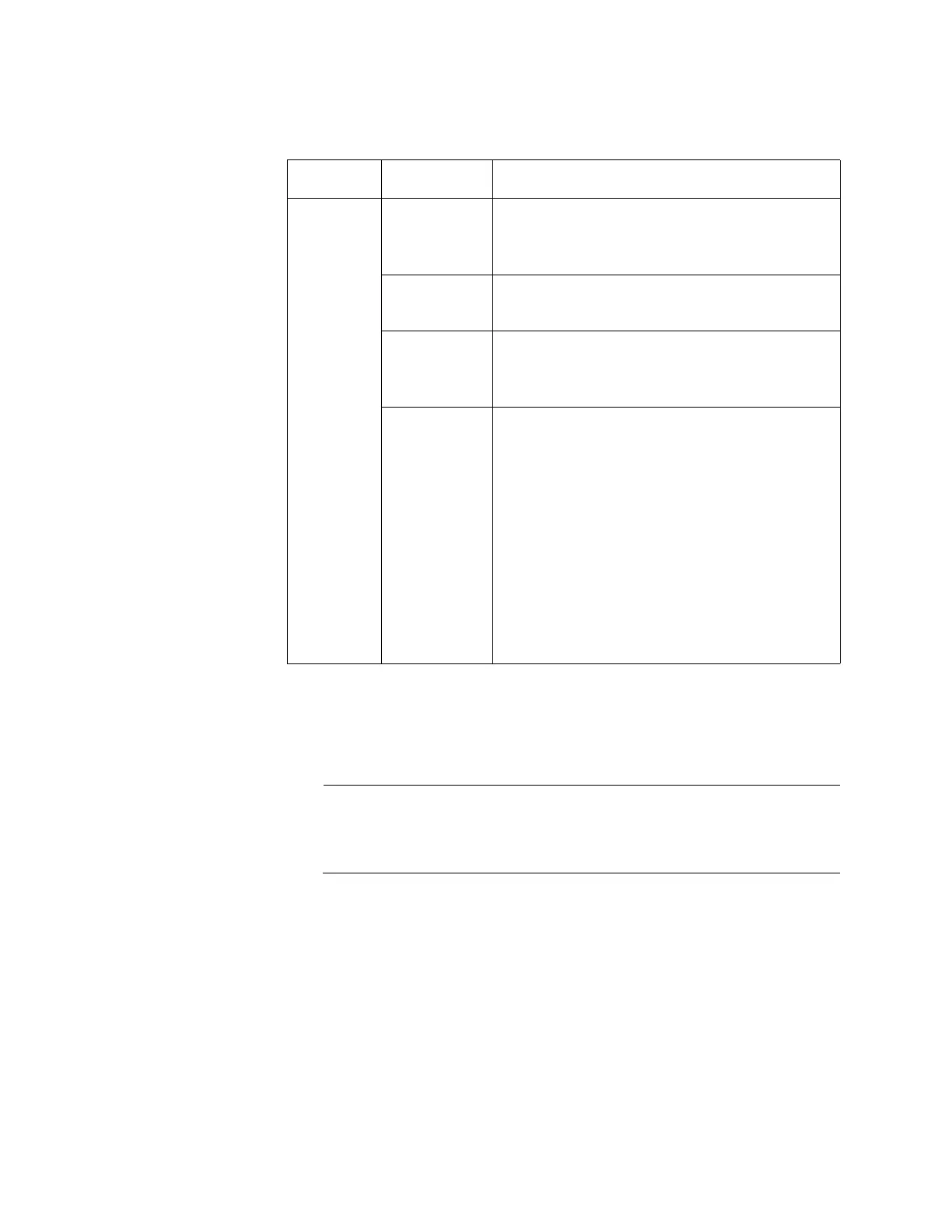
PoE Green The switch is detecting a powered device
(PD) on the port and is delivering power to
it.
Solid Amber The switch has shut down PoE+ on the port
because of a fault condition.
Flashing
Amber
The switch is detecting a PD on the port but
is not delivering power to it because the
maximum power budget has been reached.
Off This LED state can result from the following
conditions:
The port is not connected to a PD.
The PD is powered off.
The port is disabled in the
management software.
PoE is disabled on the port.
The LEDs on the Ethernet line cards
are turned off. To turn on the LEDs,
use the eco-friendly button.
Table 7. LEDs for the PoE Twisted Pair Ports on the AT-GS924MPX and
AT-GS948MPX Switches (Continued)
LED State Description

 Loading...


