Allied Construction Products, LLC Technical Manual Ho-Pac 300, 300B & 500, 500B
SECTION 6.0
MOUNTING INFORMATION
Table 6.1
Ho-Pac Mounting Specifications
Mounting Pin
Diameter
Inch [mm]
Varies with mounting bracket
*Varies with
Pin Kit (See
Table 6.2)
Mounting Pin
C-C
Inch [mm]
Varies with mounting bracket
Maximum
Stick Width
Inch [mm]
Varies with mounting bracket
6.1 Types of Mounting Frames
Ho-Pac models 300, 300B, 500 & 500B, are
light-weight and compact, which make them
ideal for use on small excavators. The Top
Mounting Frame provides attachment points
for connecting the Ho-Pac to the stick of the
carrier.
A variety of mounting frame options are
available to attach the compactor to the
carrier. Available Top Mounting Frames
include:
Flat-Top (Configured with IN1 & IN2,
XR Hole Pattern)
Excavator Side Frame - XSF
6.1.1 Flat Top Mounting Frame
Refer to Figure 7-1. When configured with
the Flat-Top mounting frame, the Ho-Pac is
attached to the desired carrier through the
use of a bolt-on mounting bracket. The Ho-
Pac models 300, 300B & 500B utilize the
“IN1” and “IN2” and “XR” bolt hole pattern.
Refer to Figures 6-1 (300, 300B) and 6-3
(500B) for dimensions.
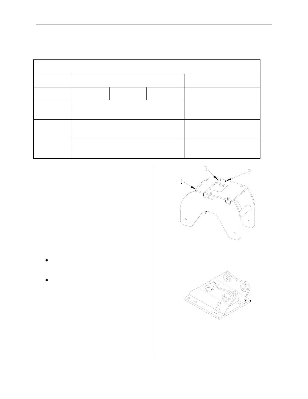
Fig. 6-1
1) Flat Top Mounting Frame, 2) “IN1” Mounting
Holes, 3) “IN2” & “XR” Mounting Holes
Fig. 6-2
Top Mounting Bracket
Allied offers an array of mounting brackets
to fit virtually any carrier, including carriers