508228-01 Issue 2136 Page 35 of 41
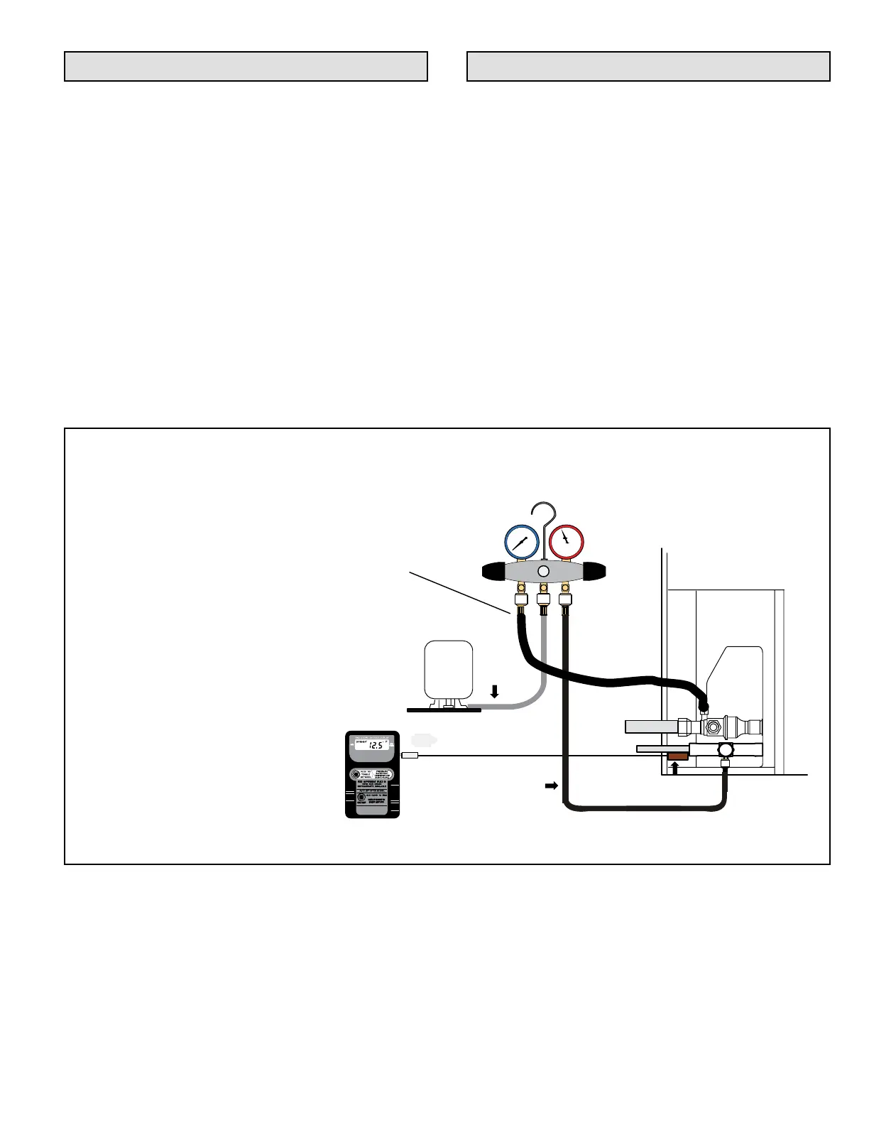
TO LIQUID
LINE SERVICE
VALVE
TEMPERATURE
SENSOR
DIGITAL SCALE
REFRIGERANT TANK
TEMPERAT URE SENSOR
(LIQUID LINE)
MANIFOLD GAUGE SET
AClose manifold gauge set valves and connect the
center hose to a cylinder of HFC-410A. Set for
liquid phase charging.
BConnect the manifold gauge set's low pressure
side to the suction line service port.
CConnect the manifold gauge set's high pressure
side to the liquid line service port.
DPosition temperature sensor on liquid line near
liquid line service port.
OUTDOOR UNIT
CHARGE IN
LIQUID PHASE
CONNECTIONS FOR TESTING AND CHARGING
GAUGE SET
A
C
D
LOW
HIGH
B
SUCTION LINE
SERVICE PORT
CONNECTION
Servicing Units Void of Charge
If the outdoor unit is void of refrigerant, clean the system
using the procedure described below.
1. Leak check system using procedure outlined on Page
24.
2. Evacuate the system using procedure outlined on
Page 24.
3. Use nitrogen to break the vacuum and install a new
lter drier in the system.
4. Evacuate the system again using procedure outlined
on Page 24.
5. Weigh in refrigerant. Refer to data plate and line set
length for proper charge.
System Refrigerant
This section outlines procedures for:
1. Connecting gauge set for testing and charging;
2. Checking and adjusting indoor airow;
3. Adding or removing refrigerant.